Battery and inverter configuration with increased efficiency

a battery and inverter technology, applied in the direction of dc-ac conversion without reversal, ac network load balancing, greenhouse gas reduction, etc., can solve the problem of increasing battery inefficiency and achieve the effect of increasing the efficiency of battery powered ac electricity supply

Active Publication Date: 2005-12-22
STEM
View PDF5 Cites 172 Cited by
  • Summary
  • Abstract
  • Description
  • Claims
  • Application Information

AI Technical Summary

Problems solved by technology

When more power is needed the battery inefficiency increases and more inverters will be activated.

Method used


Image

  • Battery and inverter configuration with increased efficiency
  • Battery and inverter configuration with increased efficiency
  • Battery and inverter configuration with increased efficiency

Examples


Embodiment Construction

[0015] The following description is demonstrative in nature and is not intended to limit the scope of the invention or its application of uses.

[0016] There are a number of significant design features and improvements incorporated within the invention.

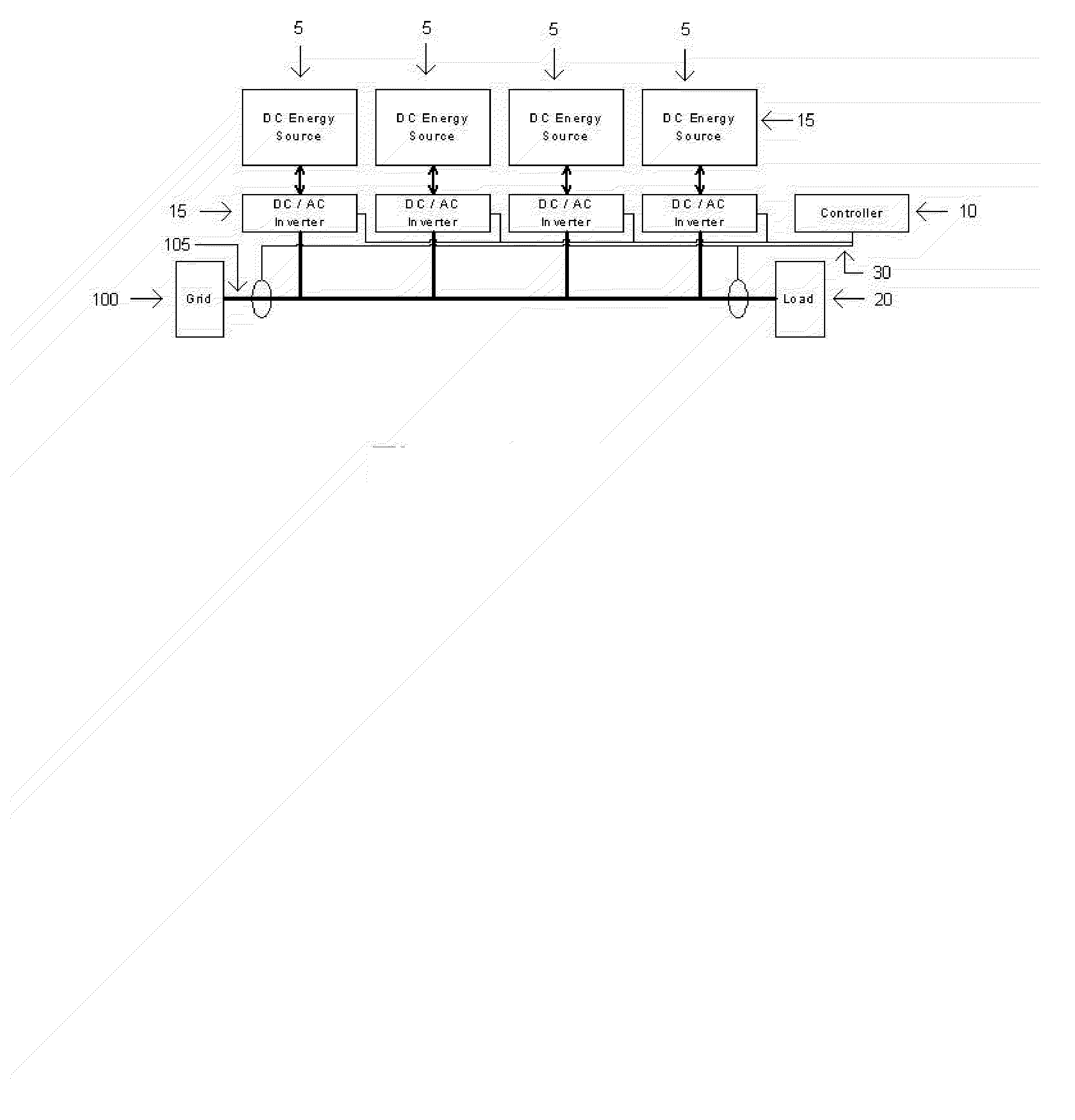
[0017] To increase efficiency of battery powered AC electricity supply, the current invention 1 has multiple inverter / battery modules that are used in parallel but can be individually shut down. The number of inverters activated depends on the power usage. When only a little power is needed only one or a few inverters are activated. When more power is needed the battery inefficiency increases and more inverters will be activated.

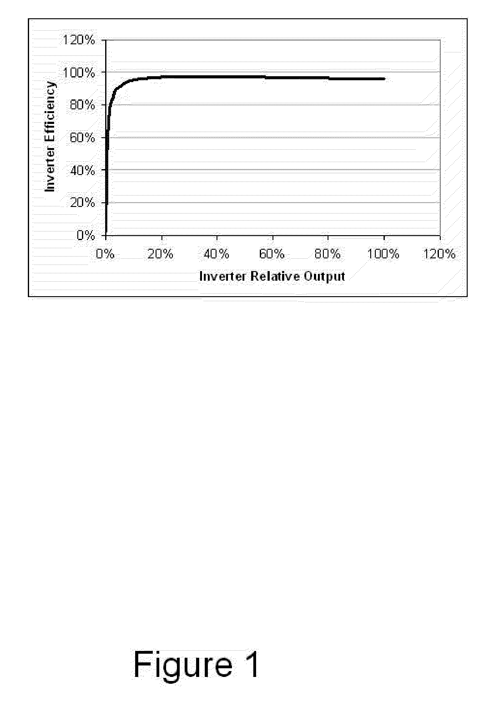
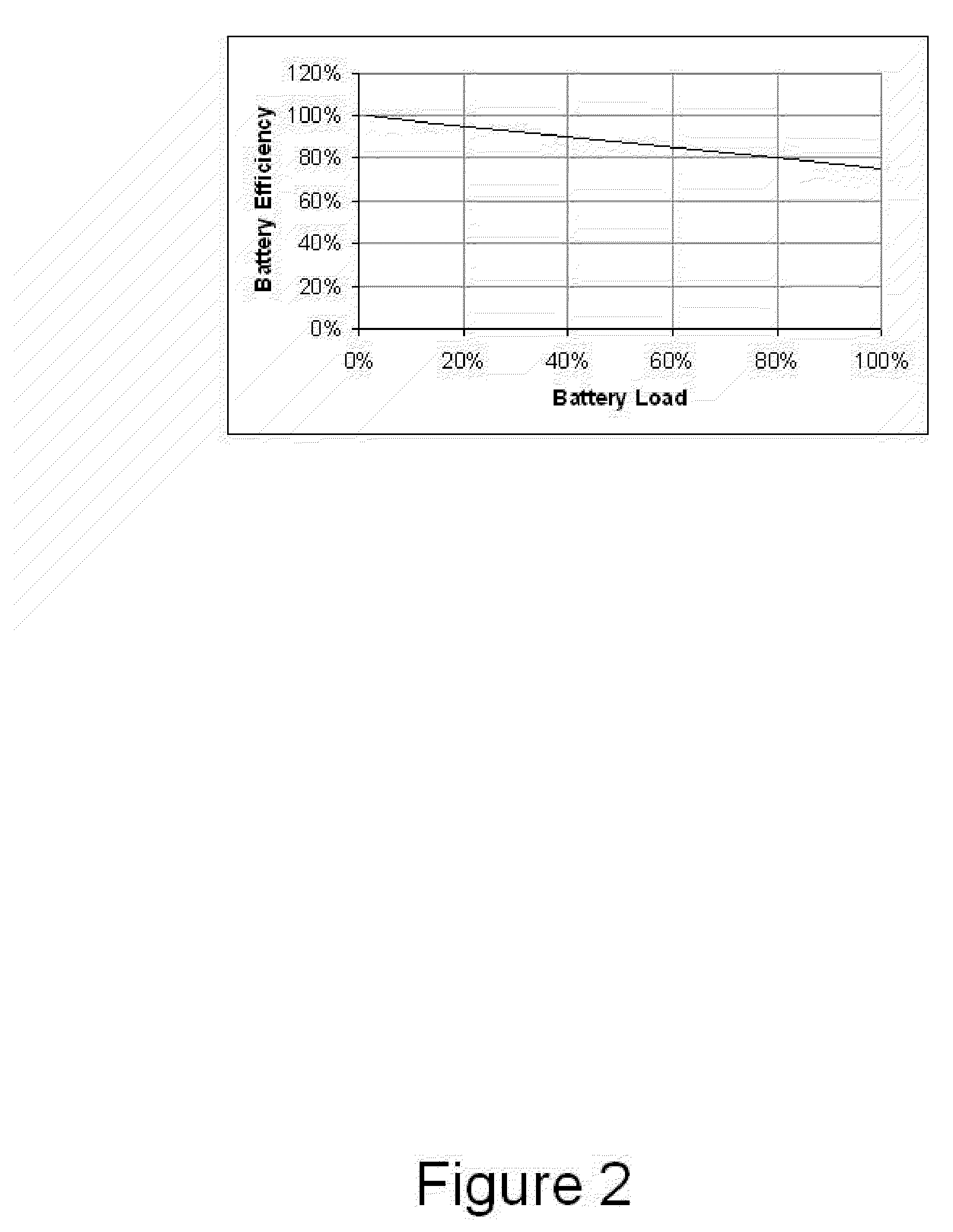
[0018]FIG. 1 displays a chart showing how the Inverter efficiency based on the relative power usage. The chart shows that inverter efficiency goes up exponentially based on inverter relative output. While FIG. 2 displays a chart that shows Battery power efficiency versus power usage. This chart shows how batt...


PUM


Abstract

In the current invention, in order to increase efficiency of battery powered AC electricity supply, multiple inverter / battery modules are used in parallel but can be individually shut down. The number of inverters activated depends on the power usage. When only a little power is needed only one or a few inverters are activated. When more power is needed the battery inefficiency increases and more inverters will be activated.

Description

BACKGROUND OF INVENTION [0001] The invention relates to battery and inverter configuration and more specifically with increased efficiency. [0002] Description of Prior Art [0003] In prior systems either one inverter is used or multiple inverters are used but are always activated so at low load the system is not very efficient. Even though multiple inverters are used only one battery string may be used and as more power is used the batteries operate more inefficient. Where only one inverter is used the system lacks redundancy and if the inverter or battery string fails the whole system fails. Some inverters may have a low stand-by power usage, but as soon as they are activated, their power consumption goes up and the efficiency at low power usage is still low. [0004] There is still room for improvement in the art. SUMMARY OF INVENTION [0005] In order to increase efficiency of battery powered AC electricity supply, the current invention has multiple inverter / battery modules that are u...

Claims


Application Information

Patent Timeline
Patent Type & Authority Applications(United States)
IPC IPC(8): H02M7/48H02M7/493
CPCH02M7/493H02J3/32H02J2300/20H02J2300/24H02J3/381Y02E10/56Y02E70/30
Inventor OLSEN, IB INGEMANNPASQUALE, NICHOLAS BLAISE
Owner STEM
Why Eureka
Try Eureka