Eye-protection apparatus, in particular retina-protection apparatus, and optical element having a free-form surface for an illumination beam path, and use of an optical element having a free-form surface

a retina-protection apparatus and optical element technology, applied in the field of retina-protection apparatus, can solve the problems of wasting heat, support material might crack, not inconsiderable portion of light loss,

Inactive Publication Date: 2005-12-22
LEICA INSTR SINGAPORE PTE
View PDF6 Cites 0 Cited by
  • Summary
  • Abstract
  • Description
  • Claims
  • Application Information

AI Technical Summary

Benefits of technology

[0009] An optical element of this kind can partially exhibit an infinite radius in its peripheral region, so that the deflection effect is absent there.

Problems solved by technology

The disadvantage here, however, is that this absorption of light by the stop in the center of the illumination beam path results in waste heat, so that, for example, the support material might crack.
In addition, a not inconsiderable portion of the light is lost as a result of the light-absorbing coating of the stop.

Method used


Image

  • Eye-protection apparatus, in particular retina-protection apparatus, and optical element having a free-form surface for an illumination beam path, and use of an optical element having a free-form surface
  • Eye-protection apparatus, in particular retina-protection apparatus, and optical element having a free-form surface for an illumination beam path, and use of an optical element having a free-form surface
  • Eye-protection apparatus, in particular retina-protection apparatus, and optical element having a free-form surface for an illumination beam path, and use of an optical element having a free-form surface

Examples


Embodiment Construction

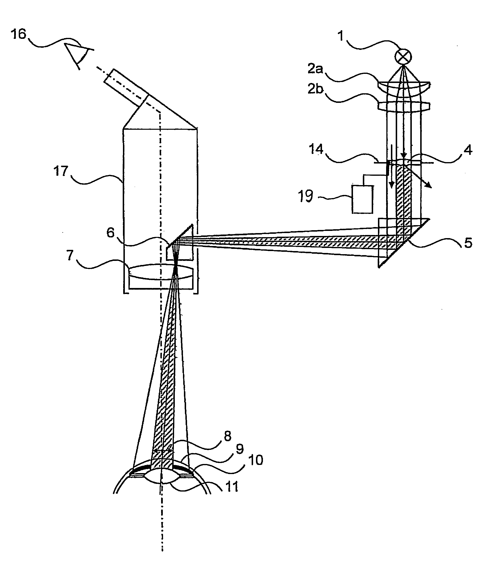
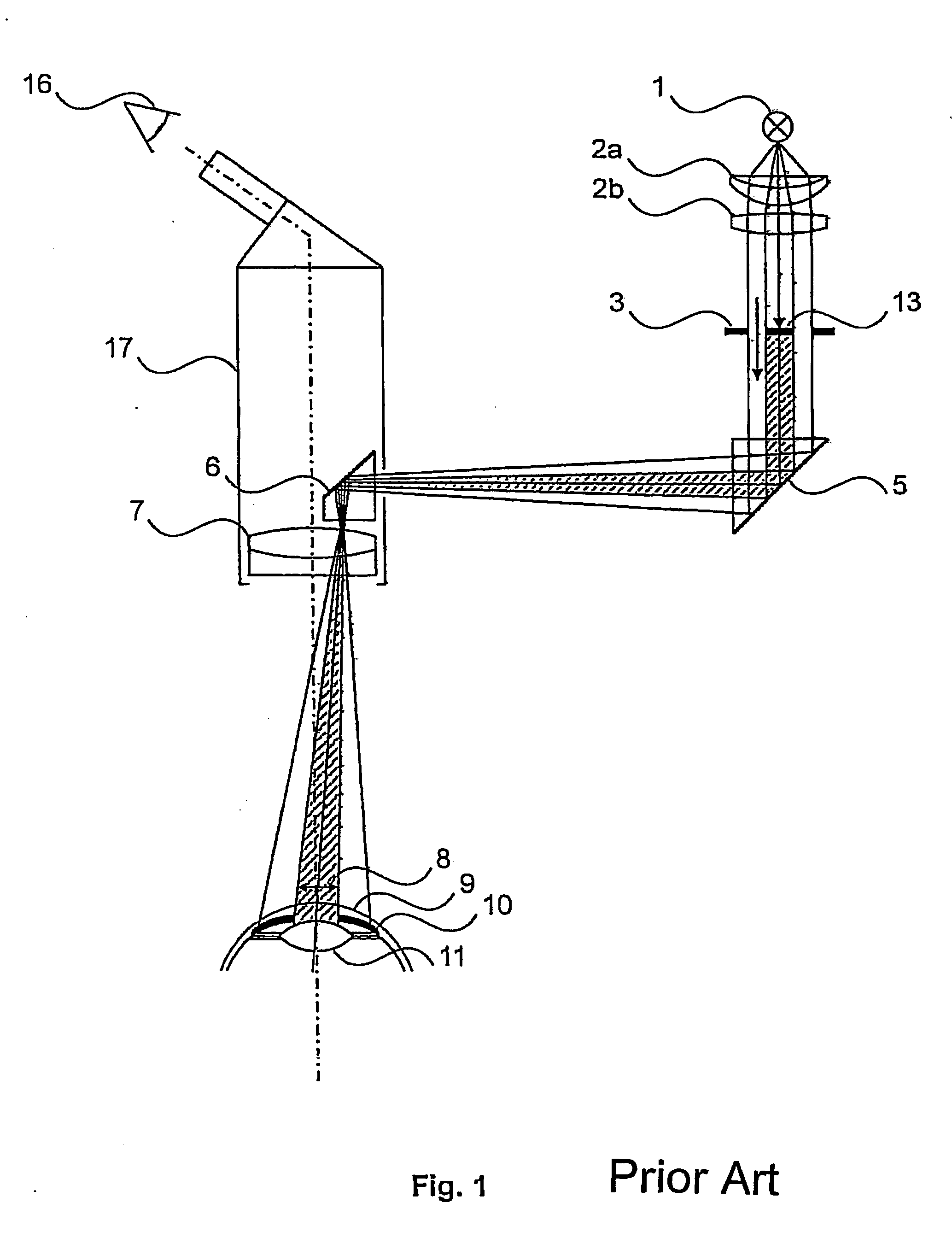
[0021]FIG. 1 depicts an illumination beam path of a microscope 17 in an application of a retina protection stop 13 according to the existing art. Light is emitted from a light source 1 into the illumination beam path, which also comprises condenser lenses 2a and 2b in the illumination beam path, thereby providing an illumination beam. A field diaphragm 3 is located in a plane conjugated with the object plane, and a retina protection stop 13 that absorbs light in the central region of the illumination beam is located in the same plane. The remaining light arrives at the surgical field by way of deflection elements 5 and 6 and an optic 7. Shadow 8 generated by retina protection stop 13 covers the pupil in iris 10 of a patient's eye. The light may therefore possibly strike iris 10 through portions of cornea 9, but does not strike the pupil or lens 11 of the patient's eye, and therefore also not the retina of that eye. Observer's eye 16 of a surgeon is also depicted.

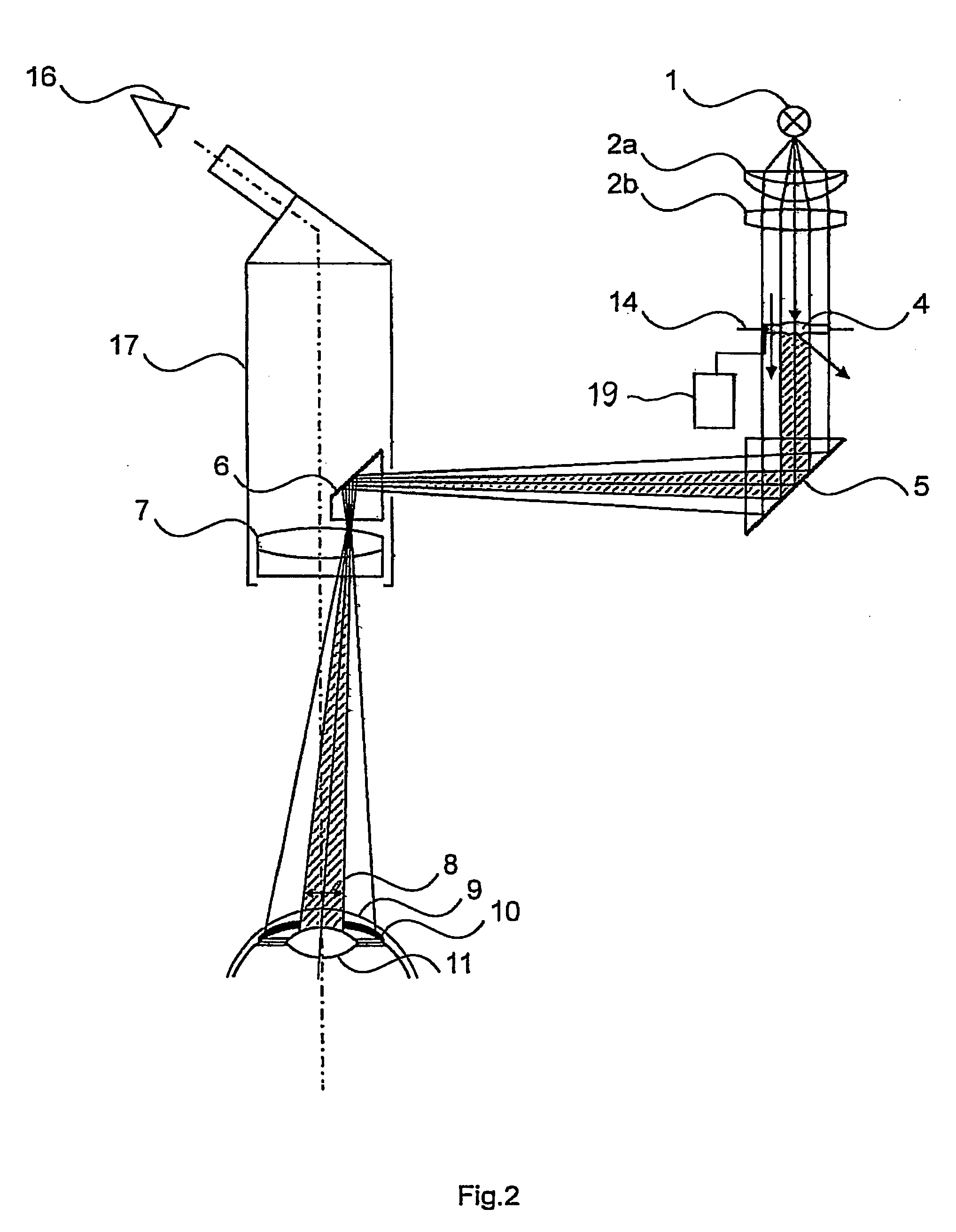
[0022]FIG. 2 depict...


PUM


Abstract

An eye-protection apparatus, in particular retina-protection apparatus, for a surgical microscope, having an illumination beam that defines an illuminated field for an object plane (14) and having an optical element (4) in the illumination beam path, wherein the optical element is embodied in such a way that it deflects light away from a central region or a decentral region of the illuminated field.

Description

CROSS REFERENCE TO RELATED APPLICATIONS [0001] This application claims priority of the German patent application 10 2004 028 470.9 filed Jun. 11, 2004 which is incorporated by reference herein. FIELD OF THE INVENTION [0002] The invention concerns an eye-protection apparatus, in particular a retina-protection apparatus, and an optical element having a free-form surface for an illumination beam path, as well as the use of an optical element having a free-form surface to protect the retina of the patient's eye in the course of eye surgery. The patient's eye needs to be protected at times from the light used by a surgeon to illuminate the surgical field on the eye. The retina, as well as the cornea and lens, could otherwise be damaged by an excessive radiation dose. BACKGROUND OF THE INVENTION [0003] Filters that filter out the damaging spectral portions of the light are usually used in surgical microscopes. [0004] DE-A1-33 39 172 describes a light trap for surgical microscopes. Zones o...

Claims


Application Information

Patent Timeline
Patent Type & Authority Applications(United States)
IPC IPC(8): A61B19/00A61B3/13A61B3/15A61F9/007G02B21/00G02B21/08
CPCA61B3/13A61B3/156G02B21/084G02B21/0012A61F9/007
Inventor SANDER, ULRICH
Owner LEICA INSTR SINGAPORE PTE
Why Eureka
Try Eureka