System for problem statement reformulation

a problem statement and problem technology, applied in the field of problem statement reformulation techniques, can solve problems such as not providing a possibility, and achieve the effect of simplifying the addition of undesirable effects

Active Publication Date: 2005-12-22
BEIJING IWINT TECH
View PDF10 Cites 0 Cited by
  • Summary
  • Abstract
  • Description
  • Claims
  • Application Information

AI Technical Summary

Benefits of technology

[0004] An exemplary embodiment of the present invention may include a system, method and computer program product which may provide an improved way of building a cause-and-effect tree related to an initial problem statement. According to an exemplary embodiment, to each event of the cause-and-effect tree there may be added one or more additional axes. In an exemplary embodiment th

Problems solved by technology

The cause-and-effect diagram systematizes reasons by categories but do

Method used


Image

  • System for problem statement reformulation
  • System for problem statement reformulation
  • System for problem statement reformulation

Examples


Embodiment Construction

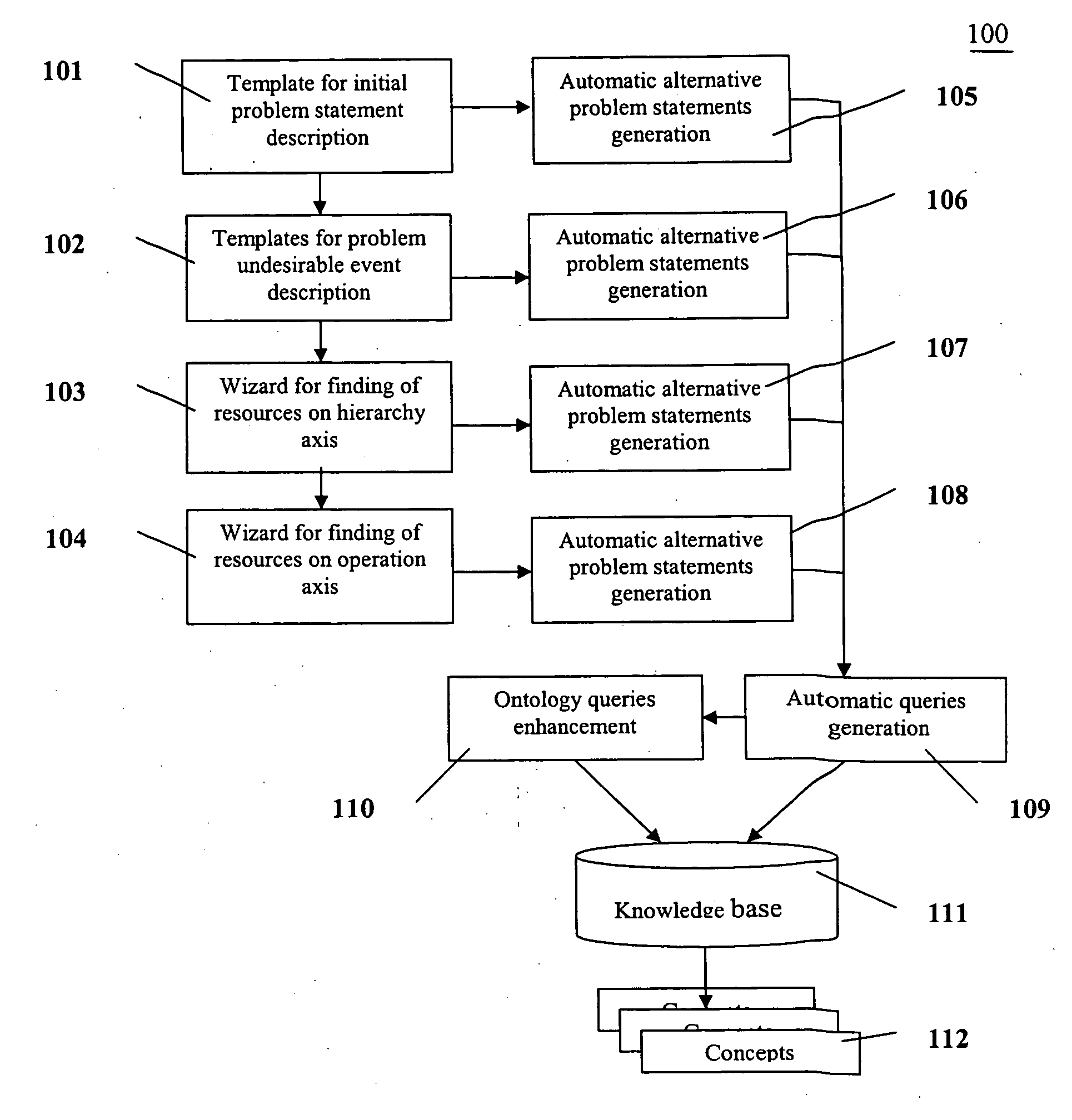
[0014] The present invention provides a more effective way to resolve problems than conventional methods. FIG. 1 depicts a diagram 100 illustrating an exemplary embodiment of the present invention. Diagram 100 may include in an exemplary embodiment, a system including, e.g., but not limited to, a template 101 to describe an initial problem statement, means to draw a cause-and-effect chain, a template 102 for description of an undesirable event, a wizard 103 for finding resources on a hierarchical axis, a wizard 104 for finding resources on an operation axis, means (105, 106, 107, and 108) for generating automatic alternative problem statements, means (109) for generating an automatic query, means 110 for ontology queries enhancement, and a knowledge base 111.

[0015] In an exemplary embodiment, system 100 may work in the following way. The User may generate an initial undesirable situation. System 100 may contain a template for supporting, e.g., 3 types of such problems. A first type...


PUM


Abstract

A method and systems that allows building cause effect tree related to initial problem statement. Each event of cause effect tree can be added with additional axes: hierarchy and operation. Wizards and templates provide simplify adding of undesirable effects. System automatically generates alternative problem statements and queries for search in knowledge bases.

Description

FIELD OF THE INVENTION [0001] The present invention relates to problem reformulation techniques. BACKGROUND OF THE INVENTION [0002] Cause-and-effect diagrams are typically used for problem reformulation and search of a root cause of an undesirable event. One of the first cause-and-effect diagrams was developed by Kauro Ishikawa of Tokyo University in 1943 and thus are often called Ishikawa Diagrams. They are also known as fishbone diagrams because of the appearance of the diagrams (in a plotted form). See, e.g., FIG. 7. Such a fishbone diagram may reflect different categories of causes. Each possible event is conventionally placed on an appropriate category line. The cause-and-effect diagram systematizes reasons by categories but does not provide a possibility to show causal links between given causes. Thus, each cause may affect one initial undesirable event, but conventionally there may be no provision to determine how multiple causes may be linked between one another. [0003] Anot...

Claims


Application Information

Patent Timeline
IPC IPC(8): G06F17/00G06N5/02G06N7/00G06N7/08
CPCG06N5/02
Inventor ZHANG, GUOMING
Owner BEIJING IWINT TECH
Why Eureka
Try Eureka