Magnetic wire pulling system

a technology of magnetic wire pulling and magnetic wire, which is applied in the direction of lifting devices, electric cable installations, instruments, etc., to achieve the effect of low production cos

Inactive Publication Date: 2005-12-29
WELKER ROBERT E
View PDF4 Cites 12 Cited by
  • Summary
  • Abstract
  • Description
  • Claims
  • Application Information

AI Technical Summary

Benefits of technology

[0020] It is another object of the present invention to provide a new and improved magnetic wire pulling system that may be easily and efficiently manufactured and marketed.
[0021] It is still another object of the present invention to provide a new and improved magnetic wire pulling system that may be readily applied to renovations and repairs in existing structures.
[0024] Even still another object of the present invention is to provide a new and improved magnetic wire pulling system that passes through less than a three quarter inch diameter hole while minimizing cosmetic and structural damage.
[0026] Even still another object of the present invention is to provide a new and improved magnetic wire pulling system that can be carried and stored in lightweight portable storage case.
[0027] Even still another object of the present invention is to provide a new and improved magnetic wire pulling system that has low production cost.

Problems solved by technology

Changing the apparent polarity of the roller magnet during rolling may cause difficulties in this method.
While the above-described devices fulfill their respective, particular objectives and requirements, the aforementioned patents and website do not describe a magnetic wire pulling system with two magnets that pulls a string beyond an obstacle and has an assortment of tools to manipulate the magnets.

Method used


Image

  • Magnetic wire pulling system
  • Magnetic wire pulling system
  • Magnetic wire pulling system

Examples


Embodiment Construction

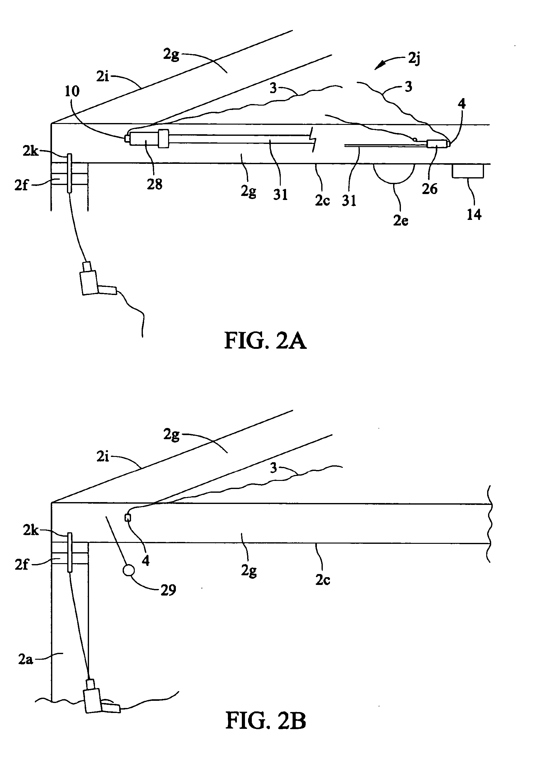
[0055] Referring now to the drawings, and particularly to FIGS. 1-13, a preferred embodiment of the magnetic wire pulling system of the present invention is shown and generally designated by the reference numeral 1.

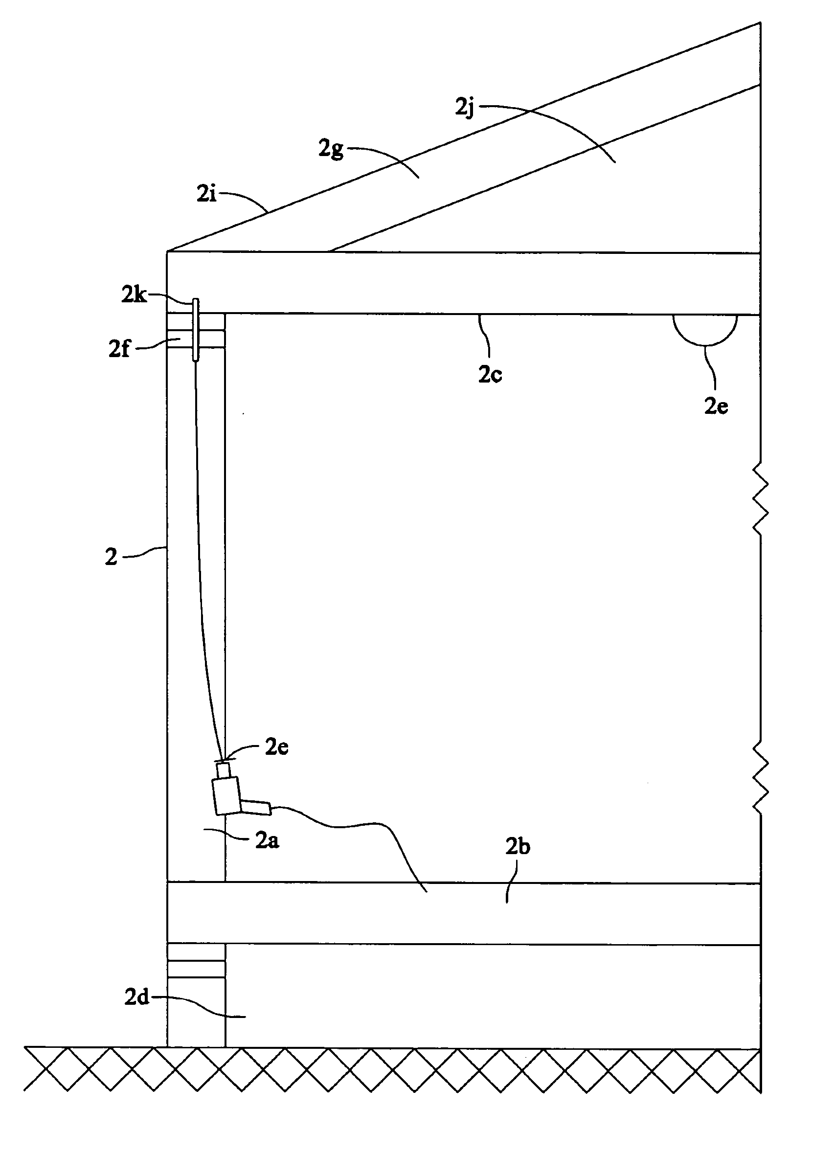
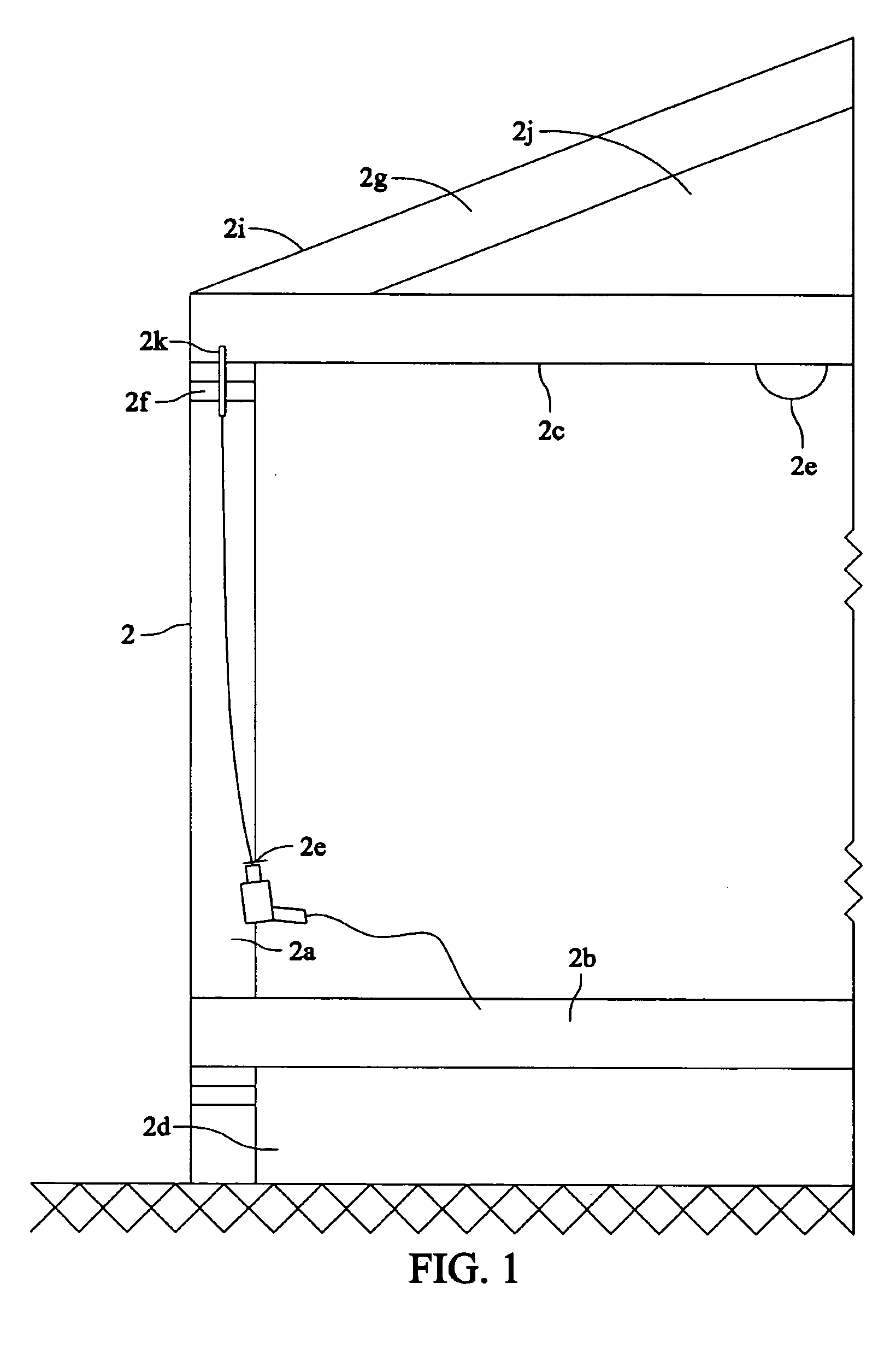
[0056] In FIG. 1, the structure of a house is shown wherein the magnetic wire pulling system 1 operates. Though the preferred embodiment of the present invention is described in reference to a house 2, the present invention can be used in other structures and locations. The present invention overcomes the obstacles inherent with the intersections of walls 2a, floors 2b, and ceilings 2c as well as difficult to access places. Thus, FIG. 1 shows a house 2 with a crawlspace 2d upon the earth. Above the crawlspace 2d, the house 2 has a floor 2b with a wall 2a at the exterior. The wall 2a has an opening for one or more fixtures 2e. The fixtures 2e can be outlet, switches, and the like. The wall 2a has a cap plate 2f upon the top opposite the floor 2b. The cap plate 2f serves a...


PUM


Abstract

A magnetic wire pulling system advances wire through a house or other structure around obstacles with a string tied to a pulling cord then tied to the wire. The system has small, medium, and large magnets, and tools attracted to the magnets. The round small and medium magnets are tied upon strings wound upon spools. The spools have pins to secure magnets. The tools comprise a retrieval tool, a manual release tool, an insertion tool, an automatic release tool, a transfer tool, an extensible prop, and a telescoping pole with magnet. The tools deliver a magnet into the structure of a house, retrieve a magnet from the structure, or transfer a magnet from one tool to another tool. In operation, a bigger magnet attracts a smaller magnet or a magnet attracts a tool to advance a string beyond an obstacle to continue pulling wire.

Description

BACKGROUND OF THE INVENTION [0001] The present invention relates to a magnetic wire pulling system for use in routing electrical wires through walls. The magnetic wire pulling system has particular utility in routing wires through corners, crawlspaces, and other difficult locations. [0002] Magnetic wire pulling systems are desirable for assisting electricians in routing conduits or wires through intersections of walls and floors, and difficult to reach places in structures. In structures, electrical wiring looks unsightly and architects and electricians labor to keep wiring hidden away. In new construction, electricians run wire through floors, walls, and ceilings before the finished surface is installed. In existing structures, electricians run wires inside finished wall, floor, and ceiling spaces. In some buildings, electricians remove ceiling tiles to run wires long distances and then drop the wires into walls. In other buildings, electricians have to fish wire between two desire...

Claims


Application Information

Patent Timeline
Patent Type & Authority Applications(United States)
IPC IPC(8): B66F3/00G10H3/00H02G1/08
CPCH02G1/085H02G1/08
Inventor WELKER, ROBERT E.
Owner WELKER ROBERT E
Why Eureka
Try Eureka