
Treadmill

a technology of treadmills and stouts, which is applied in the field of treadmills, can solve the problems of complex construction of the base, easy topple of the base, and easy tumbling of the base, so as to improve the safety of use, simplify the structure of the base, and reduce the height

Inactive Publication Date: 2005-12-29
HSIN LUNG ACCESSORIES CO LTD
View PDF6 Cites 5 Cited by
  • Summary
  • Abstract
  • Description
  • Claims
  • Application Information

AI Technical Summary

Benefits of technology

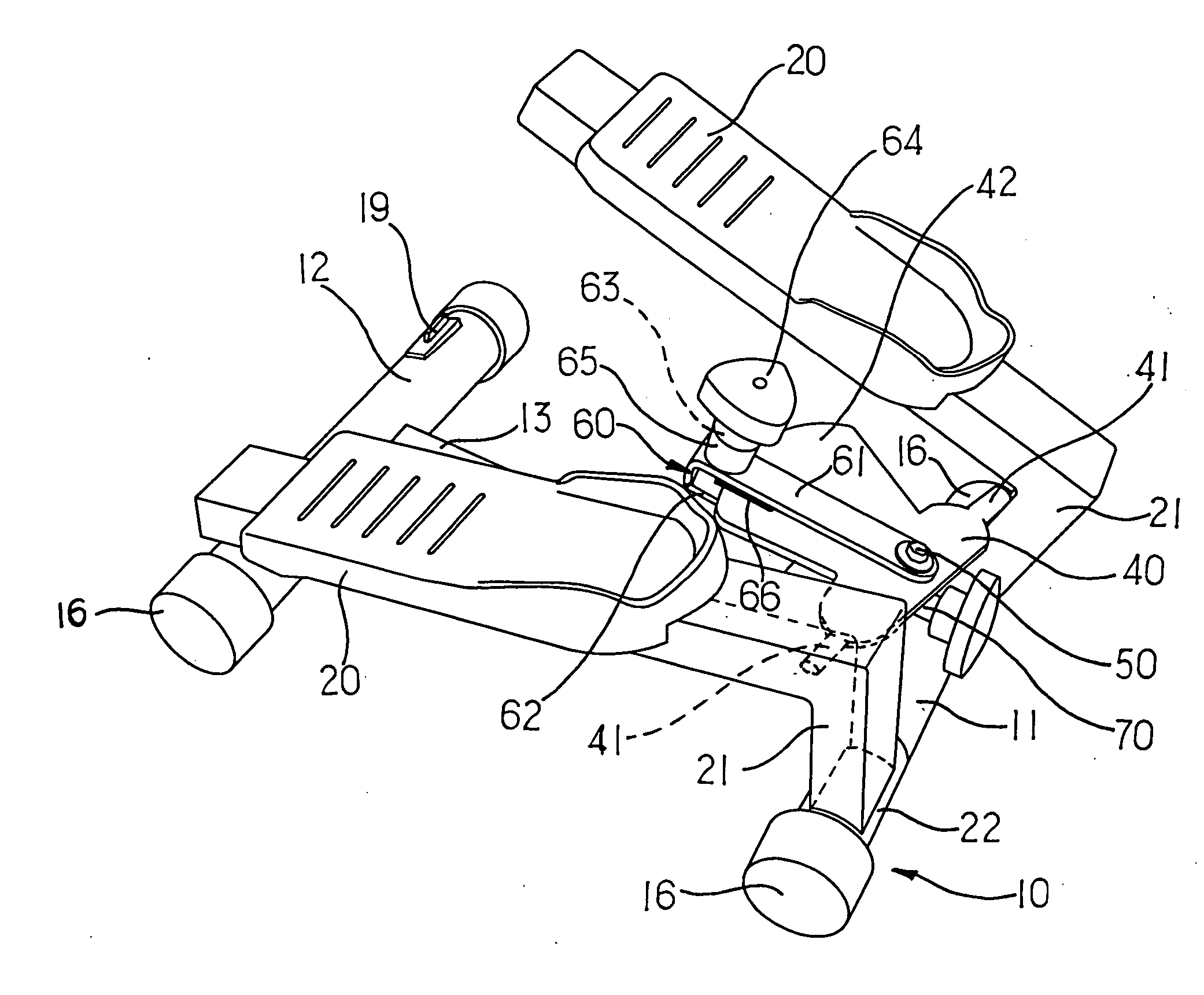
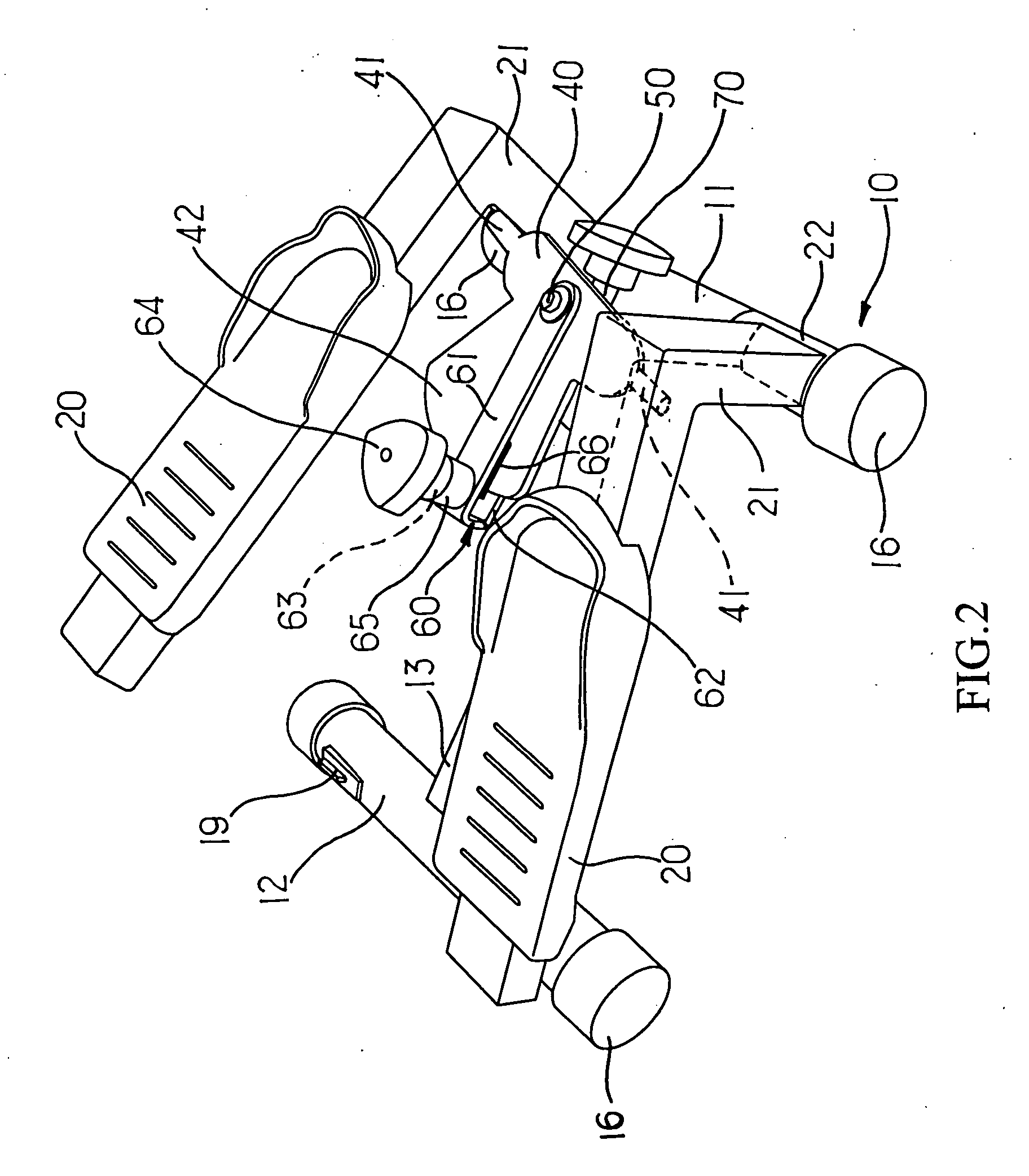
[0007] The primary purpose of the present invention is to provide an improved construction of the treadmill to simplify the structure of the base to lower its height where the force is applied making the treadmill safer to use while allowing both pedals even greater swing angle by means of a short post to upgrade the workout results. To achieve the purpose, the present invention is essentially comprised of a based and a pair of pedals. The base includes a front lever, a rear lever, a central rod connecting both centers of the front and the rear levers similar to that of the prior art. But in the present invention a short post each extends downwardly from the toe end of the pedal, and a sleeve is disposed to the tail of the short post. Both pedals are axially mounted through the sleeves to the front lever at where in relation to both ends of the central rod and both ends of the front lever are respectively provided with a sole pad to permit both pedals to swing up and down with the front lever as the axis.

Problems solved by technology

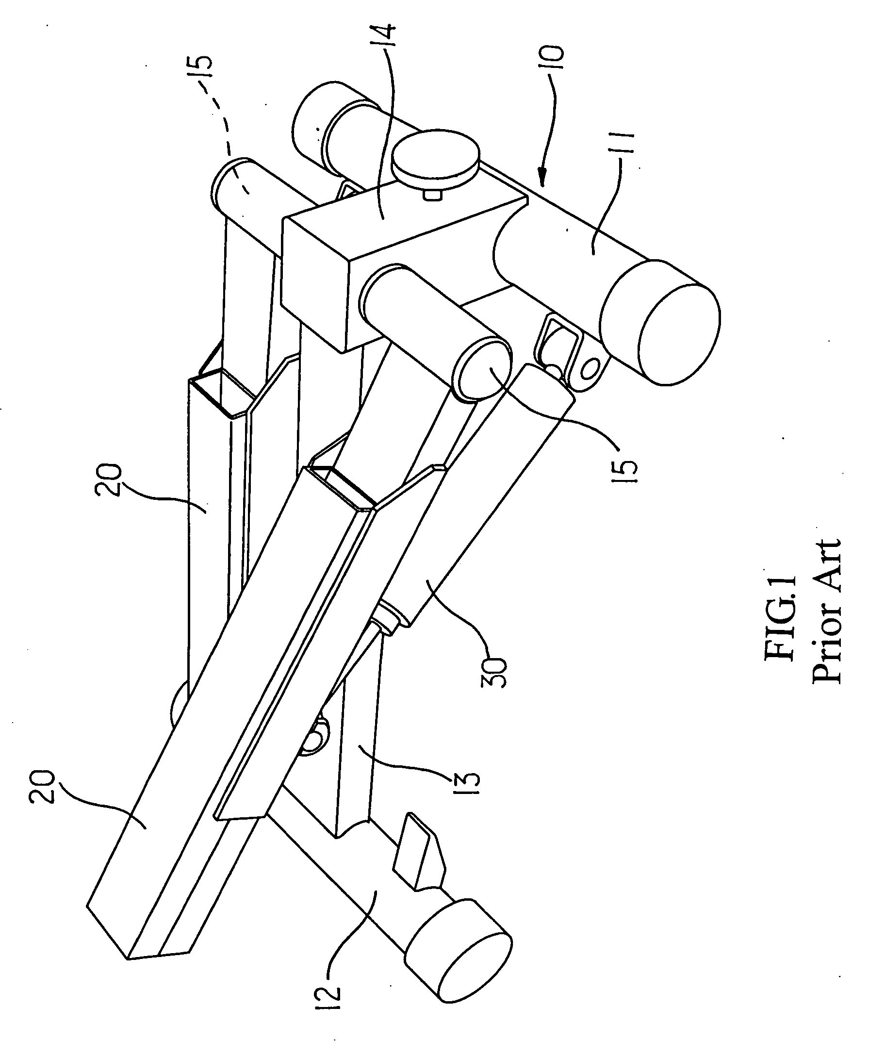
However, the construction of the base 10 tends to be complicated, and the base 10 is vulnerable to topple over since it is subject to the force only at the top of the support 14 while the force applied to both pedals 20 result in shear concentrating at where between the shaft 15 and the support 14 to break up the latter.

Method used


Image

  • Treadmill
  • Treadmill
  • Treadmill

Examples


Embodiment Construction

[0013] Referring to FIG. 2 for the basic construction of a preferred embodiment of the present invention, a base 10 is axially provided with a pair of pedals linked to each other to swing up and down for simulating the walking pattern for staying fitness purpose. As illustrated in FIG. 3, a central rod 13 extends backward from the center of a front lever 11 of the base 10, and the tail of the central rod 13 is connected to a rear lever 12 corresponding to the front lever 11 to form a base that is firmly placed on the floor.

[0014] A short post 21 disposed at its tail a sleeve 22 extends downward from a toe end of the pedal 20. Both pedals are respectively and axially mounted to the front lever 11 through their respective sleeves 22 at where in relation to both ends of the central rod 13. In the preferred embodiment, a sole pad 16 is each disposed at both ends of the front lever to prevent the sleeve 22 of the pedal contacting the ground so that both pedals 20 as illustrated inFIG. 4...


PUM


Abstract

A treadmill has one short post extending downwardly from the toe end of each of both pedals and a sleeve being provided to the tail of the short post; both pedals being respectively mounted to a front lateral lever at the bottom of a base; both ends of the lever being capped; both pedals alternatively swings up and down with the lever as the axis to simplify the construction of the base while allowing wider swing angle for both pedals to effectively reduce the height of the base subject to force, thus to make the treadmill safety to use.

Description

BACKGROUND OF THE INVENTION [0001] (a) Field of the Invention [0002] The present invention is related to a treadmill, and more particularly to one that is simple in construction, and safe and reliable in operation while allowing both pedals greater swinging angle. [0003] (b) Description of the Prior Art: [0004] Whereas most fitness equipments generally available in the market simulate the motion patterns of outdoor sports, the user of the fitness equipment is able to work out within a confined room while achieving the equivalent fitness results in the open air. For example, a treadmill allows it user to alternatively tread on both pedals in simulating the walking pattern to achieve the purposes of sports and staying fit. [0005] As illustrated in FIG. 1 of the accompanying drawings, a treadmill of the prior art is essentially comprised of two pedals 20 having their front ends pivoted to a base 10. Both pedals 20 are further connected to a hydraulic cylinder 30 so to alternatively swi...

Claims


Application Information

Patent Timeline
Patent Type & Authority Applications(United States)
IPC IPC(8): A63B21/012A63B22/00A63B22/04A63B22/16A63B23/04
CPCA63B21/012A63B21/00069A63B21/1492A63B22/0056A63B21/4047
Inventor LIAO, HSUEH-SEN
Owner HSIN LUNG ACCESSORIES CO LTD
Learn More