Apparatus and method for improving the accuracy of navigated surgical instrument

a surgical instrument and navigation technology, applied in the field of computer assisted surgery system, can solve the problems of unreliability of the final position of the jig hole, difficulty in insertion of the screws farthest from the im rod insertion hole, and numerous x-ray images,

Inactive Publication Date: 2005-12-29
STRYKER EURO OPERATIONS HLDG LLC
View PDF16 Cites 12 Cited by
  • Summary
  • Abstract
  • Description
  • Claims
  • Application Information

AI Technical Summary

Benefits of technology

[0011] Accordingly, one objective of the present invention is to provide a computer assisted surgery system for positioning an instrument relative to a portion of a surgical implant. More specifically, it assists a surgeon in drilling a hole through a long bone and through transversely oriented holes in an intramedullary rod (IM rod) during a fracture fixation procedure regardless of deformation of the IM rod.
[0012] Another objective of the invention is to provide a technique and apparatus for accurately displaying the trajectory of the drill relative to the holes of the IM rod.
[0013] Still another objective of the invention is to provide a technique and apparatus for using x-ray images of the IM rod to accurately determine the locations of the holes.
[0014] These and other objects of the present invention are achieved by the use of a computer assisted surgery system, including a computer, a localizing device and a display monitor. The system also includes a tracked adapter attached to the IM rod and a drill guide, both of which have their poses determined by the localizer. With the IM rod inserted in a long bone, and the tracked adapter attached to the exposed end of the IM rod the pose of the adapter and the IM rod are measured by the localizing device. Two approximately orthogonal x-ray images are then obtained of the IM rod in the vicinity of the holes. Image processing techniques are used to accurately determine the location of the IM rod from the x-ray images and an adjusted pose is calculated for the IM rod. A graphic representation of the drill trajectory is displayed superimposed over the images of the IM rod and over a graphic representation of the IM rod, in order to assist the surgeon in placing the drill in the proper position relative to the IM rod holes.

Problems solved by technology

The insertion of the screws farthest from the IM rod insertion hole is currently a difficult and time consuming procedure requiring numerous x-ray images.
External jigs have been tried with little success because inaccuracies in the jig, inaccuracy of the mounting between jig and IM rod, and deformation of the IM rod accumulate to cause the final jig hole positions to be unreliably aligned with the IM rod holes.
Another difficulty with existing image guided systems is that the surgeon must align the drill guide while viewing an “end on” representation of the drill guide, which can be quite challenging.
These devices, however, require equipment dedicated to this one surgical task, require the extra step of inserting an emitter to the level of the hole, and typically provide only rudimentary “end on” representations of the drill trajectory.

Method used


Image

  • Apparatus and method for improving the accuracy of navigated surgical instrument
  • Apparatus and method for improving the accuracy of navigated surgical instrument
  • Apparatus and method for improving the accuracy of navigated surgical instrument

Examples


Embodiment Construction

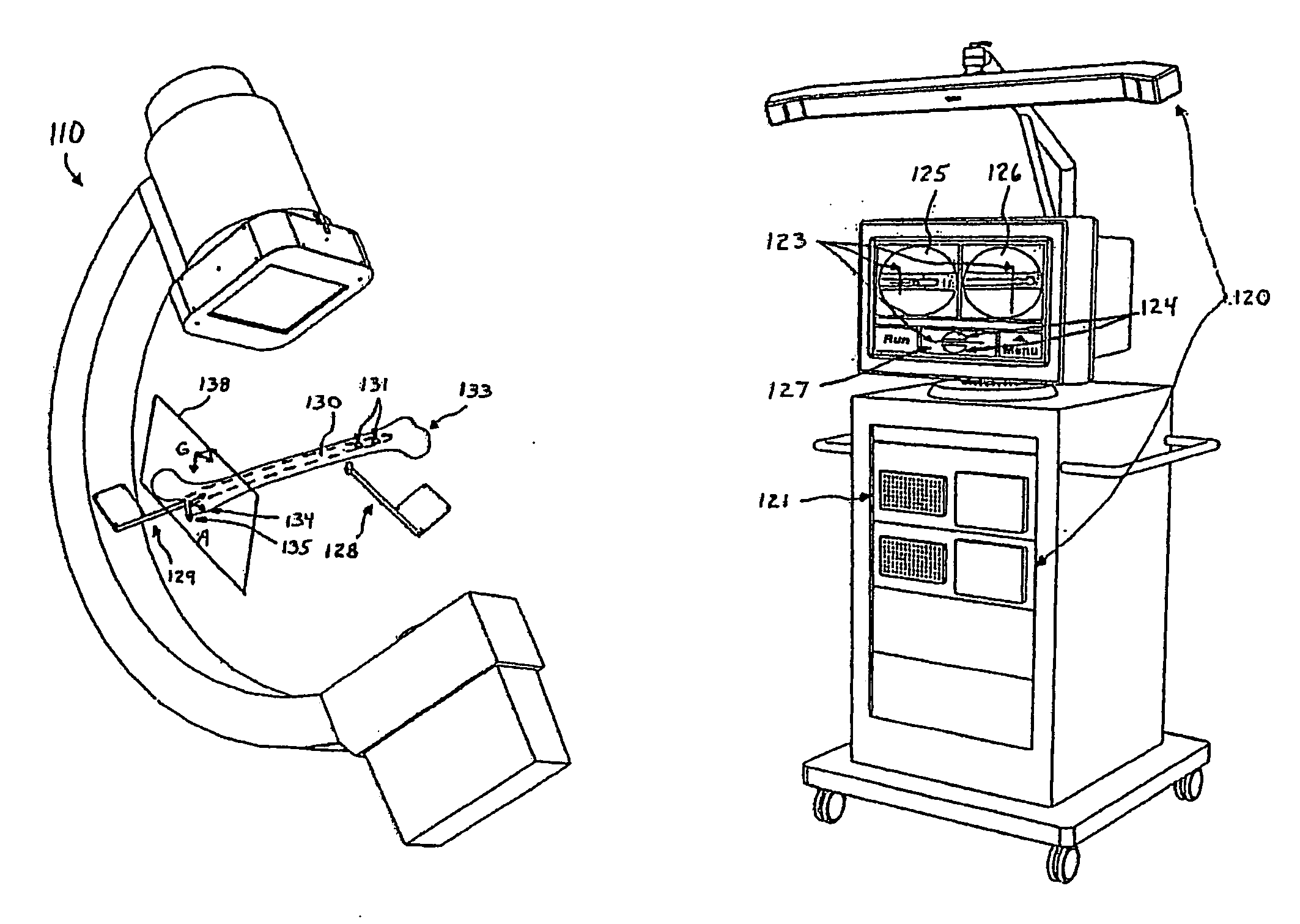
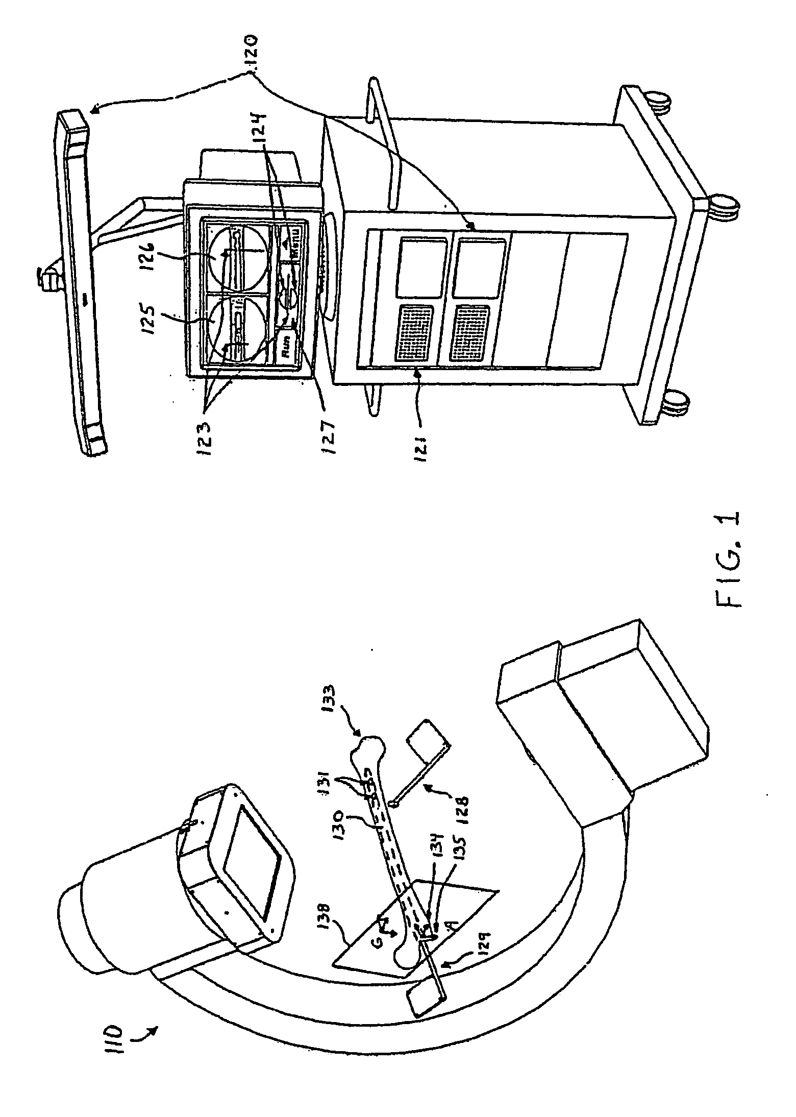
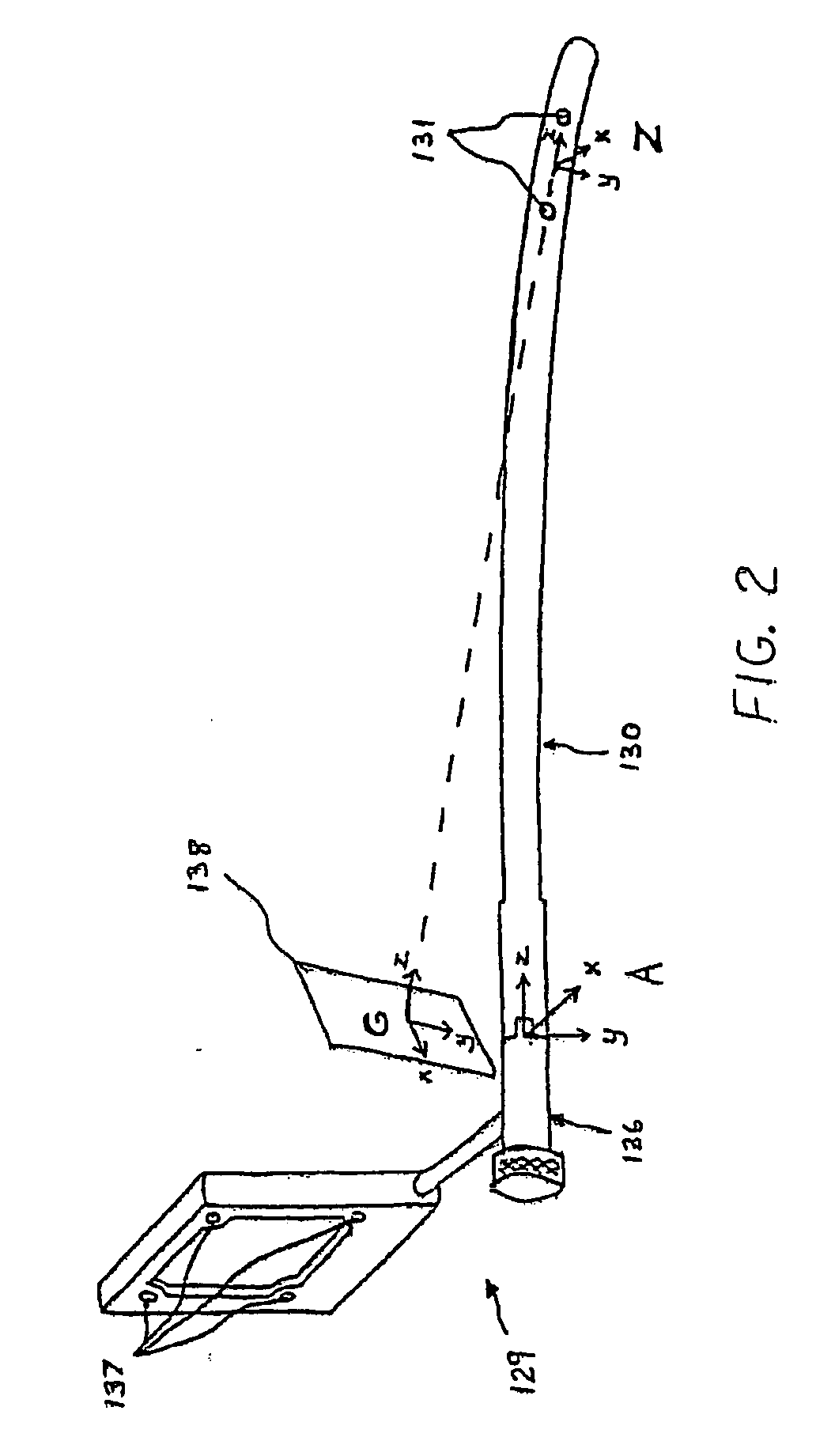
[0020] An embodiment of the image guided system of U.S. Pat. No. 6,285,902 teaches a system for placing distal interlocking screws in an IM rod. As shown in FIG. 1, the system is based on a computer (121) that receives input from an x-ray imaging device (110) and a localizing device (120), and displays surgical instrument representations (123) over x-ray images (125 and 126) in real time. A tracked adapter (129) is attached to the exposed end of the inserted IM rod (130) such that the pose of the rod can be tracked. A drill guide (128) is also tracked, and a representation of its trajectory (123) is overlaid on x-ray images (125 and 126) of the IM rod (130). Additionally, the system displays, in a separate window (127), the drill guide trajectory (123) relative to a graphical representation (124) of a cross-section of the IM rod (130) at the level of the transverse interlocking holes (131) by projecting models of these instruments onto a picture plane (138). During the procedure, th...


PUM


Abstract

A computer assisted surgery system is described for assisting a surgeon in aligning a drill with the interlocking holes of an implanted intramedullary (IM) rod used for fixation of long bone fractures. With the IM rod inserted, a localizing device measures the pose of a tracked adapter attached to the rod's exposed end. Approximate AP and lateral fluoroscopic x-ray images are acquired of the end of the rod with the interlocking holes. Image processing algorithms determine the actual position of the rod and calculate an adjustment to the pose of the tracked adapter and IM rod. Using the adjusted pose information, the system displays, in three roughly orthogonal views, a representation of the drill trajectory relative to the images of the IM rod and relative to a graphic representation of the IM rod.

Description

RELATED APPLICATIONS [0001] This application claims the benefit of U.S. application Ser. No. 09 / 683,107, filed Nov. 19, 2001, titled “Computer Assisted Intramedullary Rod Surgery System With Enhanced Features,” which claims the benefit of U.S. Provisional Application No. 60 / 249,697 filed Nov. 17, 2000. The disclosures of the 107 and 697 applications are hereby incorporated in their entirety.FEDERALLY SPONSORED RESEARCH OR DEVELOPMENT [0002] [Not Applicable]MICROFICHE / COPYRIGHT REFERENCE [0003] [Not Applicable]BACKGROUND OF THE INVENTION [0004] This invention relates to a computer assisted surgery system for use in inserting interlocking screws in an intramedullary rod. [0005] A current surgical treatment for fractures of the shaft of long bones (e.g., femur and tibia) is the insertion of an intramedullary rod (IM rod). These devices are relatively rigid devices inserted into one end of the bone and down the center canal of the bone shaft, such that the fracture site is bridged. Tran...

Claims


Application Information

Patent Timeline
Patent Type & Authority Applications(United States)
IPC IPC(8): A61B17/17A61B19/00
CPCA61B17/1703A61B17/1725A61B19/50A61B19/5244A61B2019/5265A61B2019/507A61B2019/5238A61B2019/5255A61B19/56A61B2034/2055A61B34/20A61B34/25A61B2090/376A61B34/10A61B2034/107A61B2034/2065
Inventor KIENZLE, THOMAS C. III
Owner STRYKER EURO OPERATIONS HLDG LLC
Why Eureka
Try Eureka