Eureka AIR delivers breakthrough ideas for toughest innovation challenges, trusted by R&D personnel around the world.

Protective ear appliance

a technology of protective ear and earpiece, which is applied in the direction of protective garments, headwear caps, hats, etc., can solve the problems of wearer's head suffering from several problems, earmuffs being likely to slide or be uncomfortable, and gravity not helping the earmuff to remain in place, etc., to achieve the effect of providing additional stability

Inactive Publication Date: 2006-01-05
GORDINI US
View PDF22 Cites 26 Cited by
  • Summary
  • Abstract
  • Description
  • Claims
  • Application Information

AI Technical Summary

Benefits of technology

[0007] Another object of the invention is to provide an improved protective ear appliance which allows the wearer's ears to be covered with the band in the back with adjustment of the length of the protective ear appliance performed between the ends of the band and the ear protectors.
[0012] Still yet another object of the invention is to provide an improved protective ear appliance in which an additional ear hook is added the ear cups to provide additional stability in the event of high impact or activities.

Problems solved by technology

However, in many uses it was desired that the band not rest on the wearer's head as this tended to affect the wearer's hair and interfere with wearing a hat, helmet or was generally uncomfortable for the wearer.
However, when the earmuff was rotated approximately 90 degrees so that the connecting band was generally horizontal around the back of the wearer's head or in the neck region, gravity did not assist the earmuff in remaining in place and it became necessary to rely on the biasing force in the band to maintain suitable pressure.
Generally, this approach required that the band have greater tension in it, which tended to make the earmuffs less comfortable to wear and made adjustment of the ear band and particularly important as, without a good fit around the wearer's ears of the ear cup, the earmuff was likely to slide or be uncomfortable.
Prior art earmuffs which were designed to be worn with a band around the back of the wearer's head instead of on top of the wearer's head suffer from several problems.
This tends to make the earmuff in some cases too tight so that it is uncomfortable for the wearer and, in other cases, too loose so that the earmuff is likely to slide.
In addition, most of these devices have metal which can in certain circumstances be uncomfortable and dangerous in use and require that the frame of the device be enclosed in a pocket or fabric enclosure.
In addition, these devices are generally not constructed in a fashion in which the ear cups are protective of the ear apart from providing some insulation and temperature protection.

Method used


Image

  • Protective ear appliance
  • Protective ear appliance
  • Protective ear appliance

Examples


Embodiment Construction

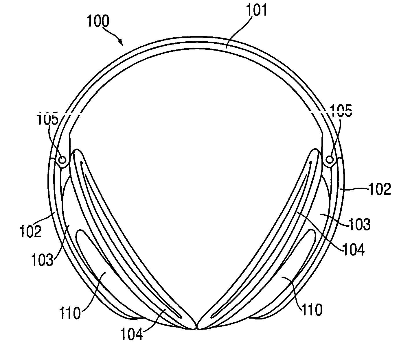
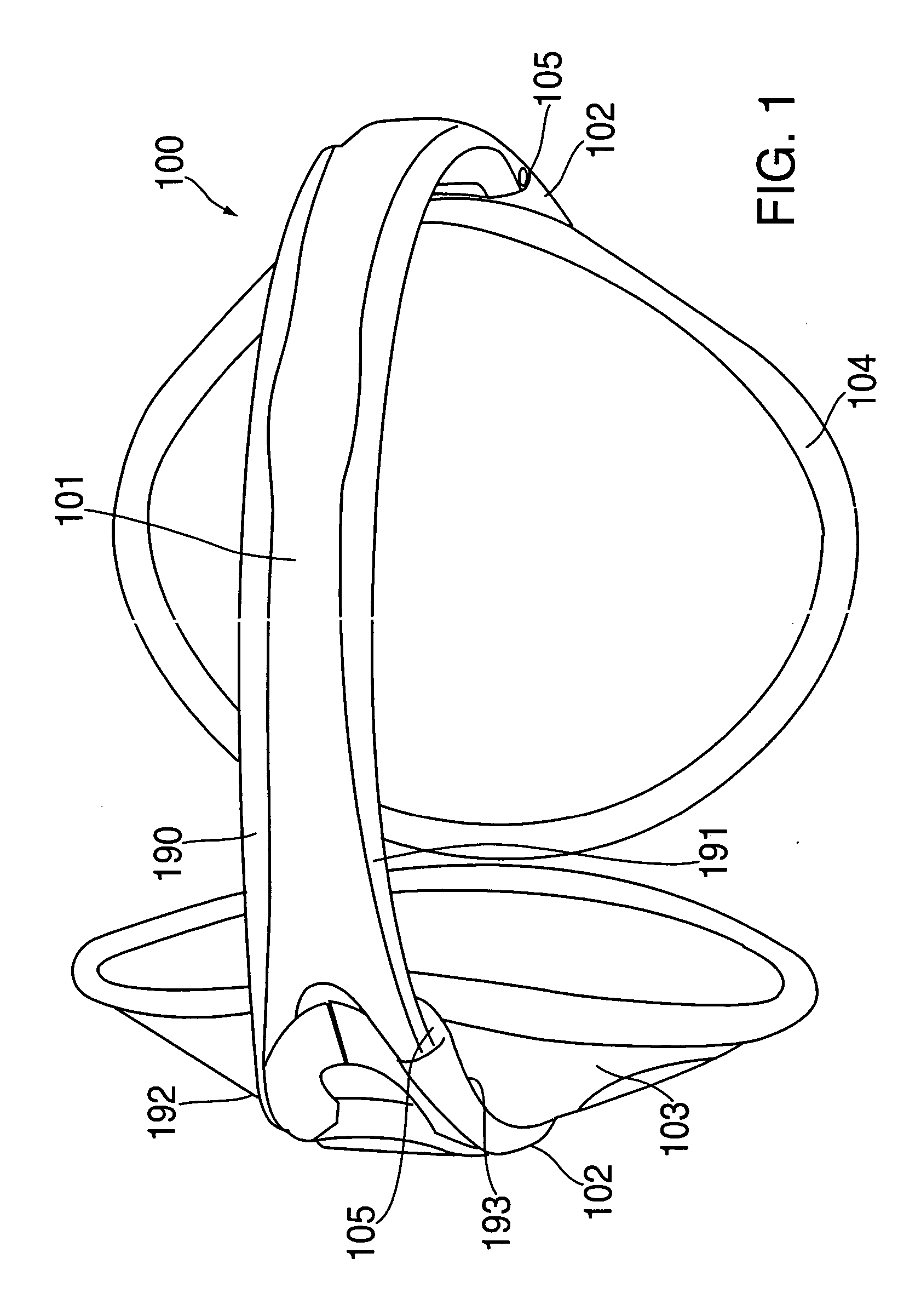
[0038] References first made to FIG. 1 wherein a protective ear appliance generally indicated as 100 constructed in accordance with a preferred embodiment of the invention is depicted. Protected ear appliance 100 includes a center band 101, two end band sections 102, two ear pieces 103, two caps 104, which fit on ear pieces 103, and two hinges 105 connecting center band 101 with each of end band sections 102. Ear pieces 103 are slidably secured to end band sections 102 and can adjust the relative length of the distance between ear caps 103 around a band sections 101 and 102 by each earpiece being slidably adjustable relative to each of the end band sections 102. Each earpiece 103 is independently adjustable relative to its corresponding end band section 102.

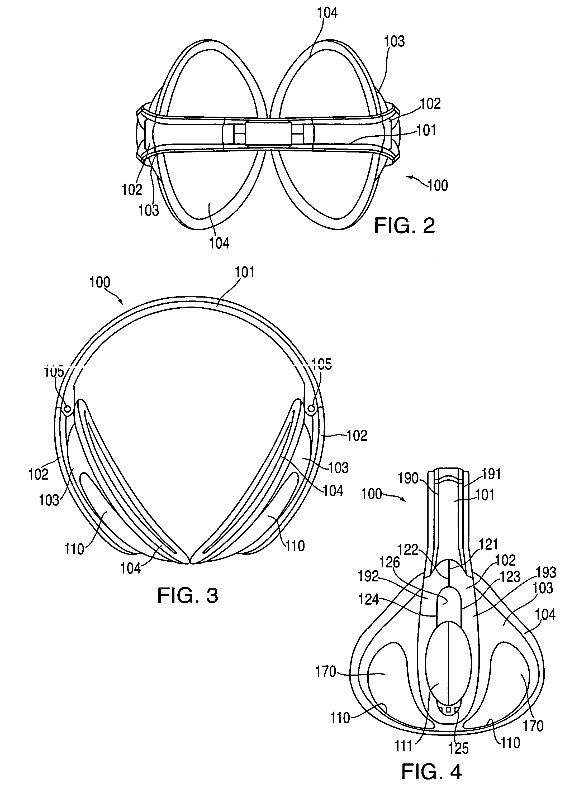
[0039] Reference is next made to FIGS. 2, 3, and 4, wherein differing views of the protective ear appliance 100 shown in FIG. 1 are depicted. Like reference numerals represent like elements. As seen in FIG. 3, center band 101 an...


PUM


Abstract

A protective ear appliance including two ear protectors with a band and a slidable coupling between the band and the ear protectors. The band encircles a portion of a wearer's head, has a curved shape with two ends and inner and outer curved surfaces. There is a slidable coupling between each of the ear protectors and the band so that each ear protector can slide independently with respect to the band to adjust the distance between the two ear protectors along the band so that the ear protectors can seat in the wearer's ears. The band can be formed with a central band hingedly coupled to the two end band portions. The ear protectors are coupled to the end band portions and slide relative to the end band portions. The protective ear appliance is designed to be worn with the central band around the back of the wearer's head.

Description

[0001] This application claims the priority of prior Provisional Patent Application Ser. No. 60 / 579,906 filed on Jun. 15, 2004.BACKGROUND OF THE INVENTION [0002] The invention is generally directed to a protective ear appliance, and, in particular, to a device, known either an earmuff or ear band, which covers the wearer's ears with cupped regions sized and shaped to cover the ears and a band between the ear cups to support the earmuff or ear band on the wearer's head. In the past, earmuffs have been generally known in which the earmuff band was generally positioned on top of the wearer's head so that gravity provided much of the ability of the earmuff to remain on the wearer's head. However, in many uses it was desired that the band not rest on the wearer's head as this tended to affect the wearer's hair and interfere with wearing a hat, helmet or was generally uncomfortable for the wearer. Of course, the traditional earmuffs were formed with a metal, spring-like band, which provid...

Claims


Application Information

Patent Timeline
Patent Type & Authority Applications(United States)
IPC IPC(8): A42B1/06
CPCA61F11/14
Inventor GELLIS, DAVIDSHAANAN, GADDUVAL, FRANCOISDUBEAU, SERGEBROUSSEAU, IVAN
Owner GORDINI US
Why Eureka
Eureka Blog
Learn More