
High integrity protective coatings

a protective coating, high-integrity technology, applied in the direction of basic electric elements, electrical equipment, semiconductor devices, etc., can solve the problems of high surface spikes, scratched and damaged exposed surfaces of these devices, and not atomically smooth substrates, etc., to achieve low permeation rates

Active Publication Date: 2006-01-05
BOE TECH GRP CO LTD
View PDF35 Cites 57 Cited by
  • Summary
  • Abstract
  • Description
  • Claims
  • Application Information

AI Technical Summary

Benefits of technology

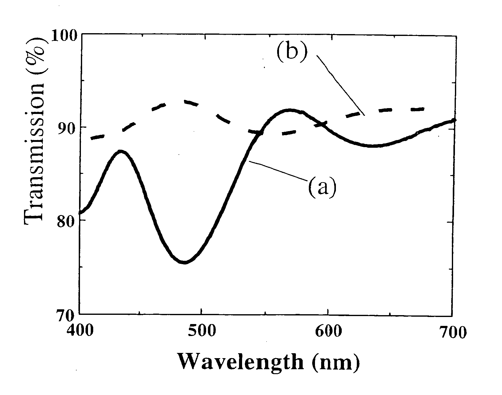
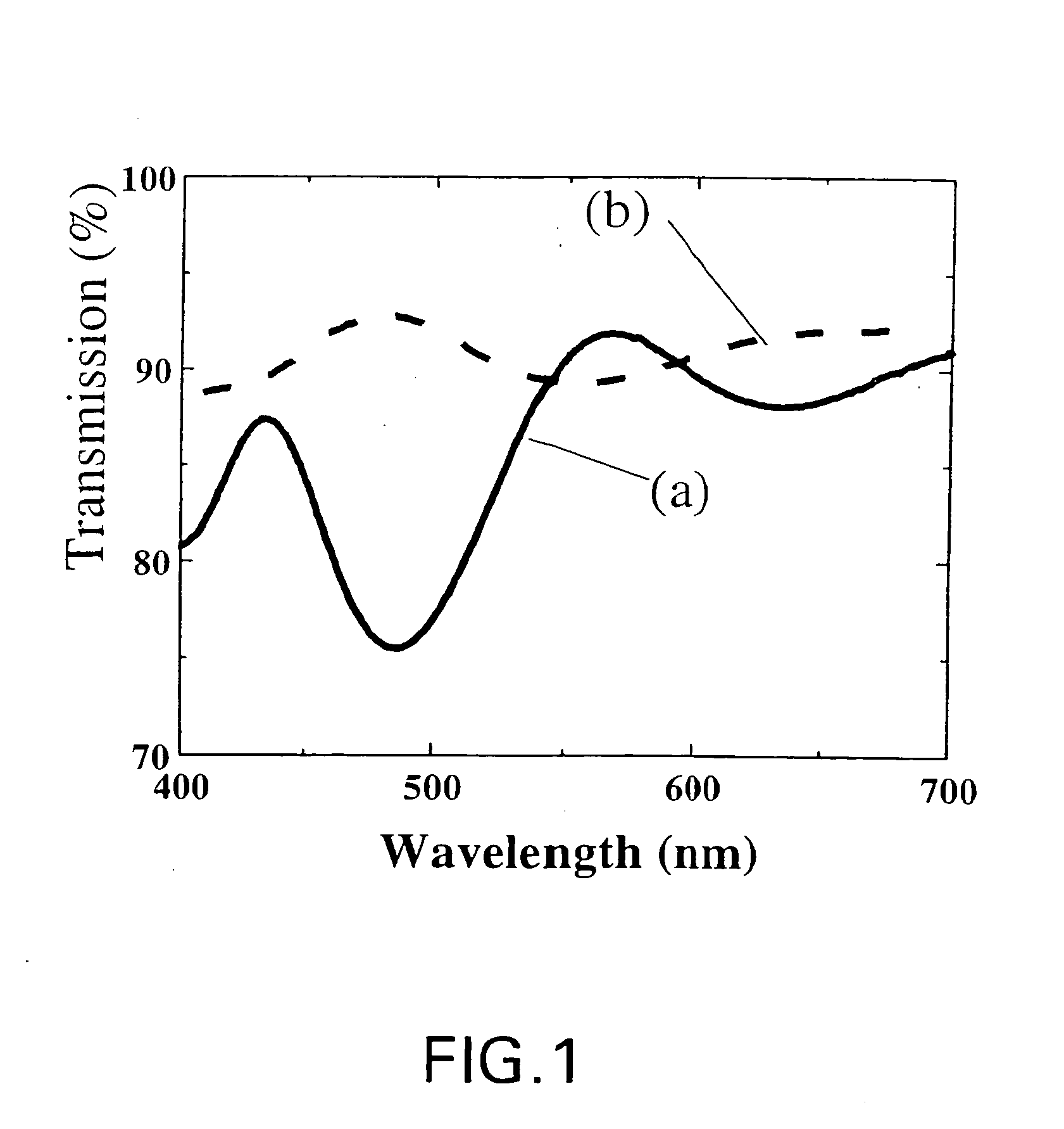
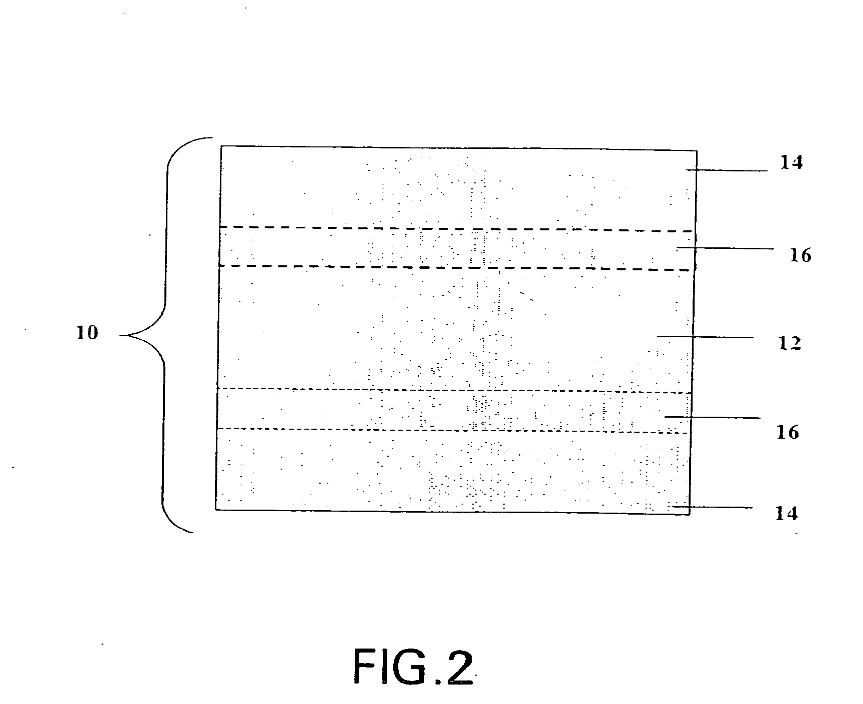
[0009] These and other features, aspects, and advantages of the present invention will become better understood when the following detailed description is read with reference to the accompanying drawings in which like characters represent like parts throughout the drawings, wherein:

Problems solved by technology

Quite often substrates, especially polymeric substrates on which these devices may be a manufactured, are not atomically smooth and have surface spikes that are hundreds of nanometers high.
Also, the exposed surfaces of these devices may be scratched and damaged during fabrication and / or transportation.
These surface defects may often limit the performance of these devices.

Method used


Image

  • High integrity protective coatings
  • High integrity protective coatings
  • High integrity protective coatings

Examples


example 1

[0079] A composition comprising 100 parts by weight liquide cycloaliphatic diepoxide (Dow Chemical ERL4221d), 1 part by weight Octacat UV sensitive catalyst (General Electric UV9392C) and 0.15 parts by weight of a surfactant (3M Fluorad FC430) were blended together, flitered through a 1 micron filter, degassed and applied to a plastic substrate by spin coating. Immediately after coating, the layer was exposed to a mercury arc lamp broadband UV source for 30 seconds which activates the catalyst and then the part was baked in an oven at 125 C for 1 hour to complete the cure of the epoxy resin. An organic-inorganic composition barrier coating layer is deposited over the planarizing layer.

example 2

[0080] A composition comprising ERL4299, Octacat UV sensitive catalyst (General Electric UV9392C) and a surfactant (3M Fluorad FC430) were blended together, flitered through a 1 micron filter, degassed and applied to a plastic substrate by spin coating. Immediately after coating, the layer was exposed to a mercury arc lamp broadband UV source for 30 seconds which activates the catalyst and then the part was baked in an oven to complete the cure of the epoxy resin. An organic-inorganic composition barrier coating layer is deposited over the planarizing layer.

example 3

[0081] A composition comprising siloxane containing epoxy such as Silar Labs Product 2283 (cycloaliphatic epoxy disiloxane), Octacat UV sensitive catalyst (General Electric UV9392C) and a surfactant (3M Fluorad FC430) were blended together, flitered through a 1 micron filter, degassed and applied to a plastic substrate by spin coating. Immediately after coating, the layer was exposed to a mercury arc lamp broadband UV source for 30 seconds which activates the catalyst and then the part was baked in an oven to complete the cure of the epoxy resin. An organic-inorganic composition barrier coating layer is deposited over the planarizing layer.


PUM


Abstract

A composite article with at least one high integrity protective coating, the high integrity protective coating having at least one planarizing layer and at least one organic-inorganic composition barrier coating layer. A method for depositing a high integrity protective coating.

Description

CROSS REFERENCE TO RELATED APPLICATIONS [0001] This application is a Continuation-In-Part of U.S. patent application Ser. No. 10 / 879,468, entitled “BARRIER COATINGS”, filed Jun. 30, 2004, which is herein incorporated by reference.STATEMENT REGARDING FEDERALLY SPONSORED RESEARCH & DEVELOPMENT [0002] This invention was made with Government support under contract number RFP01-63GE awarded by United States Display Consortium and Army Research Laboratory. The Government has certain rights in the invention.BACKGROUND [0003] The invention relates generally to protective coatings. More specifically, the invention relates to protective coatings that are used in optoelectronic devices. [0004] Optical and optoelectronic devices that are susceptible to reactive chemical species normally encountered in the environment, require protective coatings with good barrier properties. Quite often substrates, especially polymeric substrates on which these devices may be a manufactured, are not atomically ...

Claims


Application Information

Patent Timeline
IPC IPC(8): H01L29/24H01L21/44
CPCH01L51/5237H10K50/8445H01L21/32115H01L21/7684H01L2924/068
Inventor KIM, TAE WONYAN, MINHELLER, CHRISTIAN MARIA ANTONSCHAEPKENS, MARCGORCZYCA, THOMAS BERTMC CONNELEE, PAUL ALANERLAT, AHMET GUN
Owner BOE TECH GRP CO LTD
Learn More