Systems and methods for automated telescope alignment and orientation
Inactive Publication Date: 2006-01-05
FCC LLC
View PDF30 Cites 10 Cited by
Summary
Abstract
Description
Claims
Application Information
AI Technical Summary
This helps you quickly interpret patents by identifying the three key elements:
Problems solved by technology
Method used
Benefits of technology
Problems solved by technology
The first configuration might be termed a simplified configuration, and might be functionally limited in that it is able to provide direction and speed commands to the intelligent motor modules, but might only be provided with limited operational command processing capabilities so as to offer a low-cost alternative.
Method used
Image
Click on the blue label to locate the original text in one second.
Reading with bidirectional positioning of images and text.
Examples
Embodiment Construction
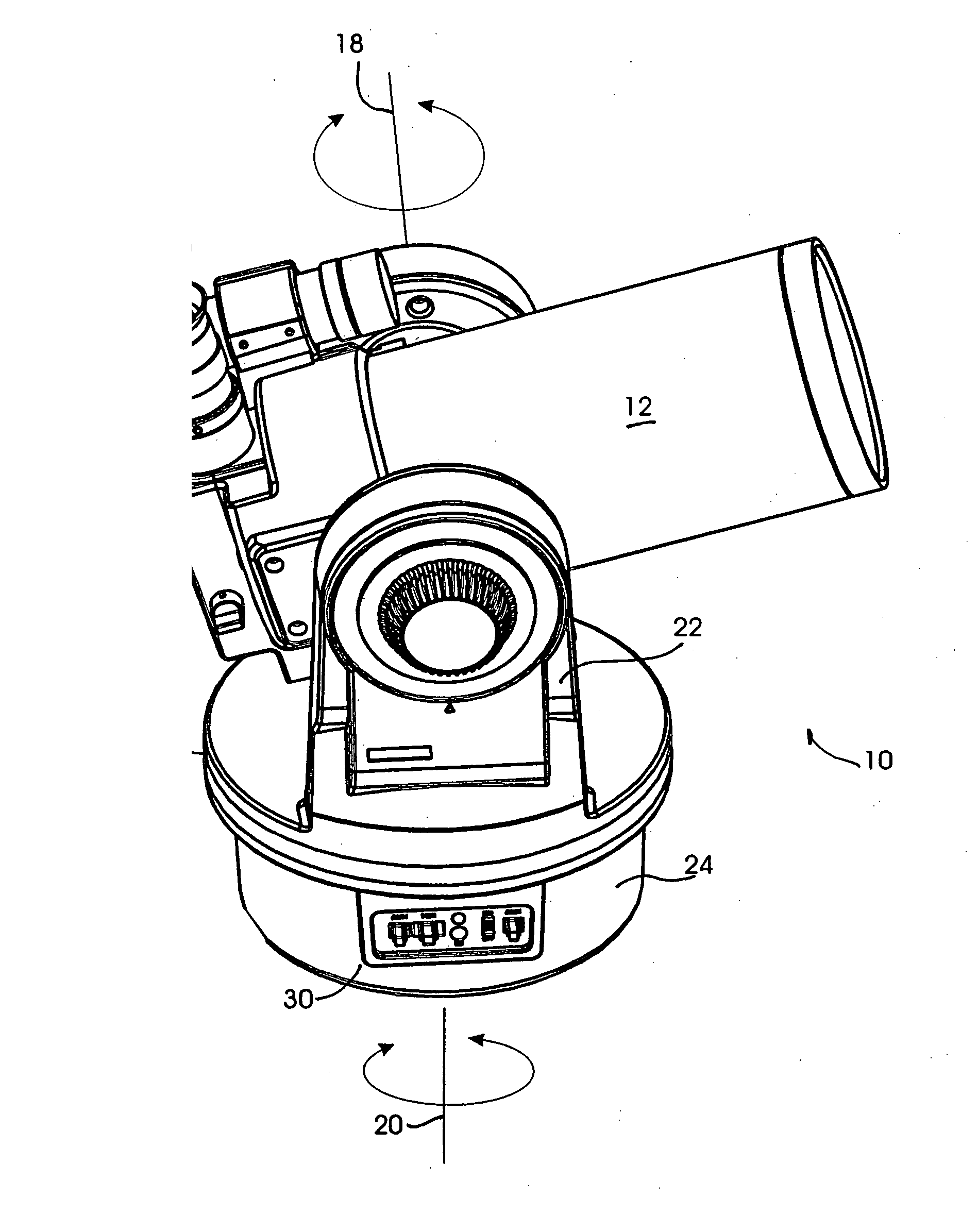
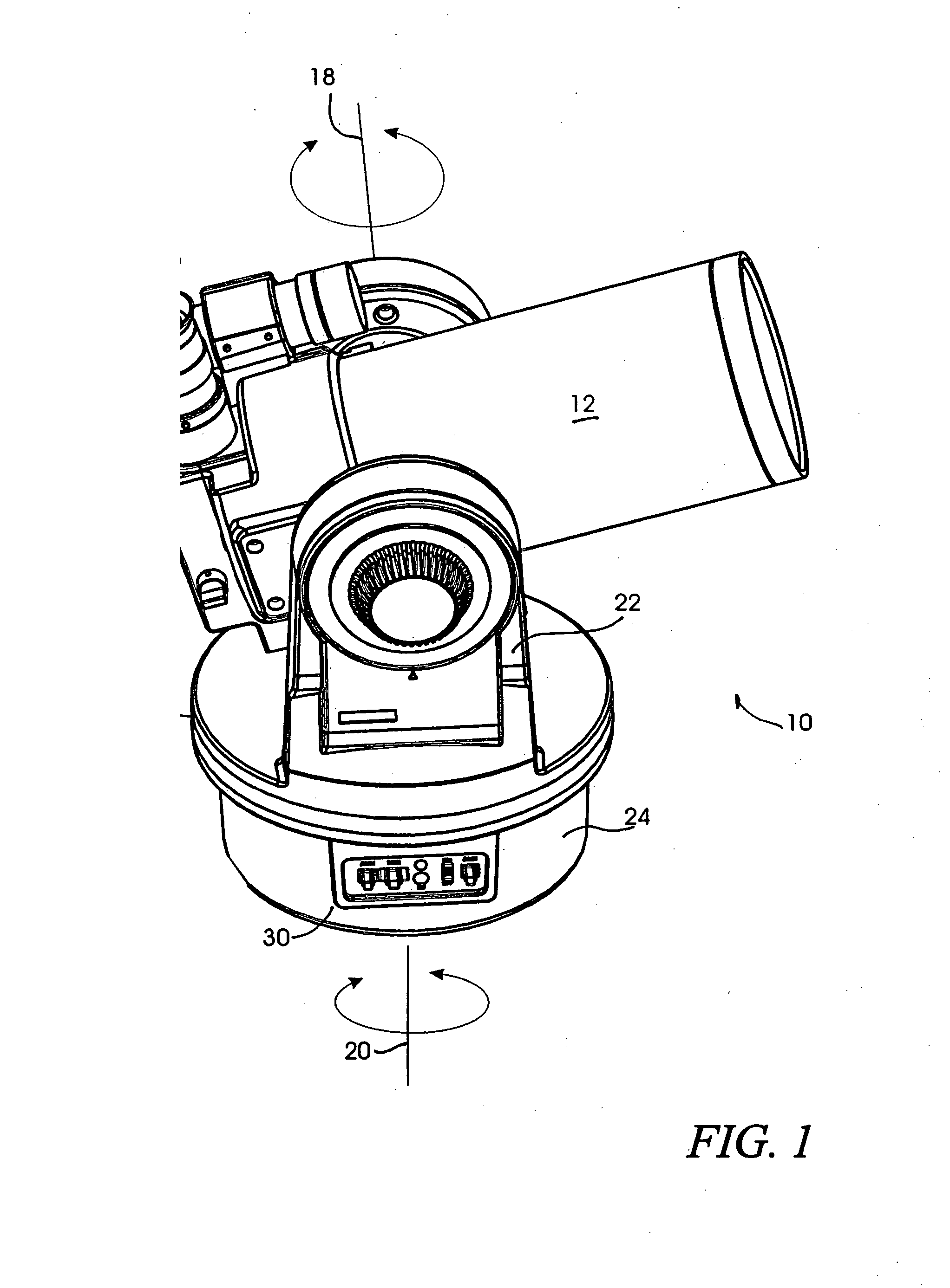
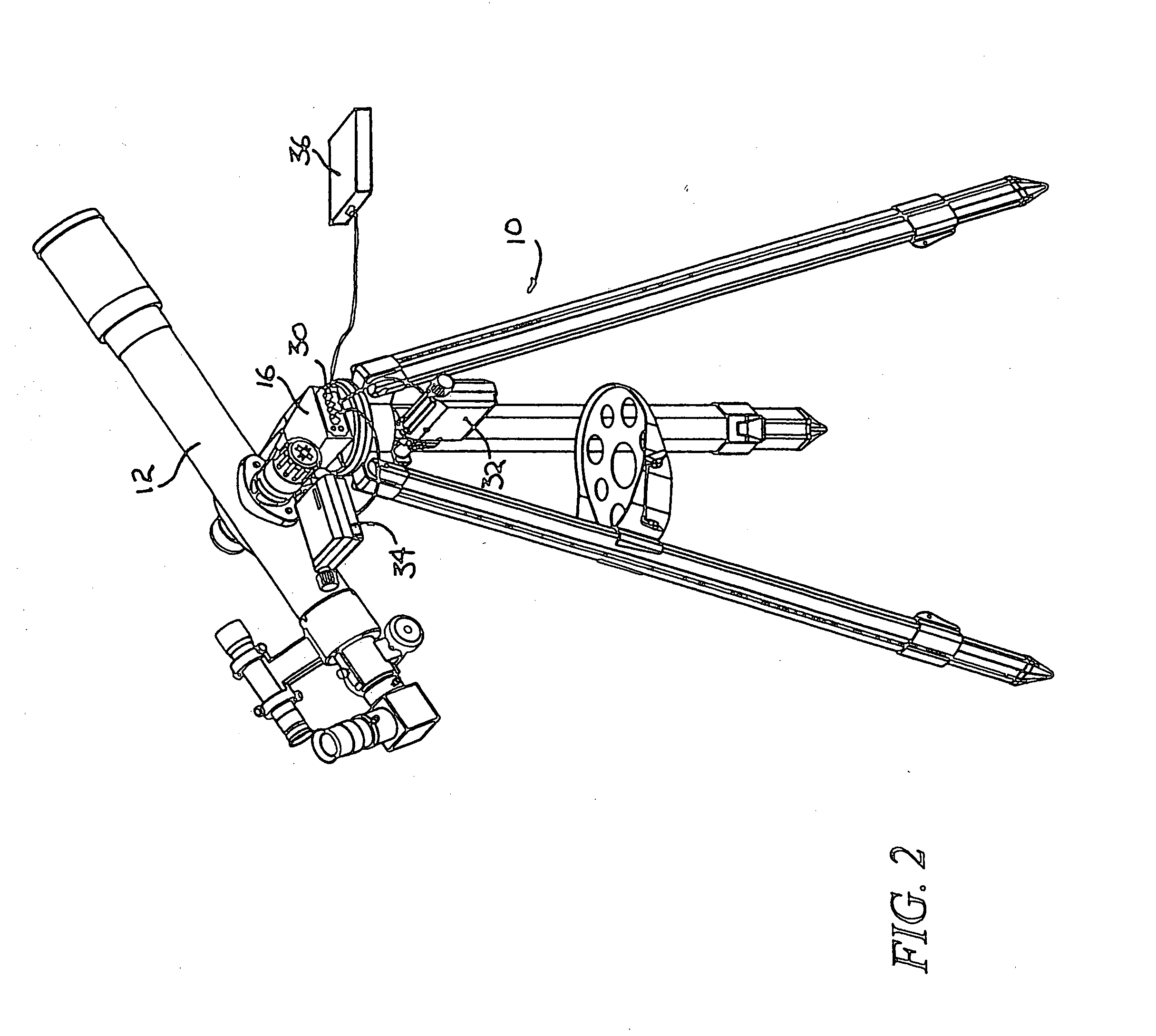
[0029] The detailed descriptions of an automated telescope system with distributed intelligence and alignment, orientation and tracking ability, set forth below in connection with the appended drawings are intended only as a description of the presently preferred and illustrated embodiments of the invention, and are not intended to represent the only form in which the present invention may be constructed or utilized. The detailed descriptions set forth the construction and function of the invention, as well as the sequence of steps utilized in its operation, in conjunction with the illustrated embodiments. It is to be understood by those having skill in the art, that the same or equivalent functionality may be accomplished by various modifications to the exemplary embodiments without departing from the spirit and scope of the invention.
[0030] An automated telescope system, with distributed intelligence and a control system for operating such a telescope, will now be described with ...
PUM
Abstract
Embodiments of an automated telescope system are operable in multiple modes, including alt-az and equatorial modes. The telescope system aligns and orients itself to the celestial coordinate system using, for example, data gained through tracking the drift of a celestial object. In various embodiments, an imager may be used to find and track celestial objects.
Description
CROSS-REFERENCE TO RELATED APPLICATIONS [0001] The present application claims priority benefit under 35 U.S.C. § 120 to, and is a continuation of U.S. patent application Ser. No. 09 / 771,385, filed Jan. 26, 2001, entitled “Systems and Methods for Automated Telescope Alignment and Orientation,” (the “Parent Application”), which is a continuation-in-part of U.S. patent application Ser. No. 09 / 428,866, filed Oct. 26, 1999, entitled “Fully Automated Telescope System with Distributed Intelligence,” now U.S. Pat. No. 6,392,799, which claims priority benefit under 35 U.S.C. § 119(e) from U.S. Provisional Application Nos. 60 / 105,626, filed Oct. 26, 1998 entitled “Fully Automated Telescope System With Distributed Intelligence,” and 60 / 143,637, filed Jul. 14, 1999, entitled “Self Orienting, Self Aligning, Intuitive Automated Telescope.” The Parent Application also claims priority benefit under 35 U.S.C. § 119(e) from U.S. Provisional Application No. 60 / 178,840, filed Jan. 26, 2000, entitled “S...
Claims
Application Information
Patent Timeline
Application Date:The date an application was filed.
Publication Date:The date a patent or application was officially published.
First Publication Date:The earliest publication date of a patent with the same application number.
Issue Date:Publication date of the patent grant document.
PCT Entry Date:The Entry date of PCT National Phase.
Estimated Expiry Date:The statutory expiry date of a patent right according to the Patent Law, and it is the longest term of protection that the patent right can achieve without the termination of the patent right due to other reasons(Term extension factor has been taken into account ).
Invalid Date:Actual expiry date is based on effective date or publication date of legal transaction data of invalid patent.
Patent Type & AuthorityApplications(United States)

