Celestial compass kit

a compass kit and kit technology, applied in the field of direction detection systems, can solve the problems of reducing the accuracy of the magnetic compasses to several degrees or rendering them useless, affecting the accuracy of the magnetic compasses, and the current target location technology does not meet this standard, so as to increase the dynamic range of the kit, the effect of minimizing the size and weight of the compass ki

Active Publication Date: 2012-07-05
TREX ENTERPRISEES
View PDF6 Cites 29 Cited by
  • Summary
  • Abstract
  • Description
  • Claims
  • Application Information

AI Technical Summary

Benefits of technology

[0012]The present invention provides a celestial compass kit. The kit includes an inclinometer, a camera system with a special telecentric fisheye lens for imaging at least one celestial object and a processor programmed with a celestial catalog providing known positions at specific times of at least one celestial object and algorithms for automatically calculating target direction information based on the inclination of the system as measured by the inclinometer and the known positions of at least one celestial object as provided by the celestial catalog and as imaged by the camera. The telecentric fisheye lens produces an image on the sensor located at or near the focal plane which remains spatially constant within sub-micron accuracies despite thermally produced changes in the focus of the lens. Preferred embodiments of the kit include a movable filter unit to increase greatly the dynamic range of the ki

Problems solved by technology

Magnetic compasses are typically accurate to only one degree, and the presence of steel or other local disturbances will often reduce accuracy of the magnetic compasses to several degrees or render them useless.
Therefore, if positioning of a target depends on the use of a magnetic compass, substantial position errors could likely result.
Current target location technology does not meet this standard.
The main source of error is magnetic compasses.
These error sources are random and cannot be accurately calibrated and modeled to subtract out.
A large magnetic disturbance from hard or soft iron effects can result in target accuracy er

Method used


Image

  • Celestial compass kit
  • Celestial compass kit
  • Celestial compass kit

Examples


Embodiment Construction

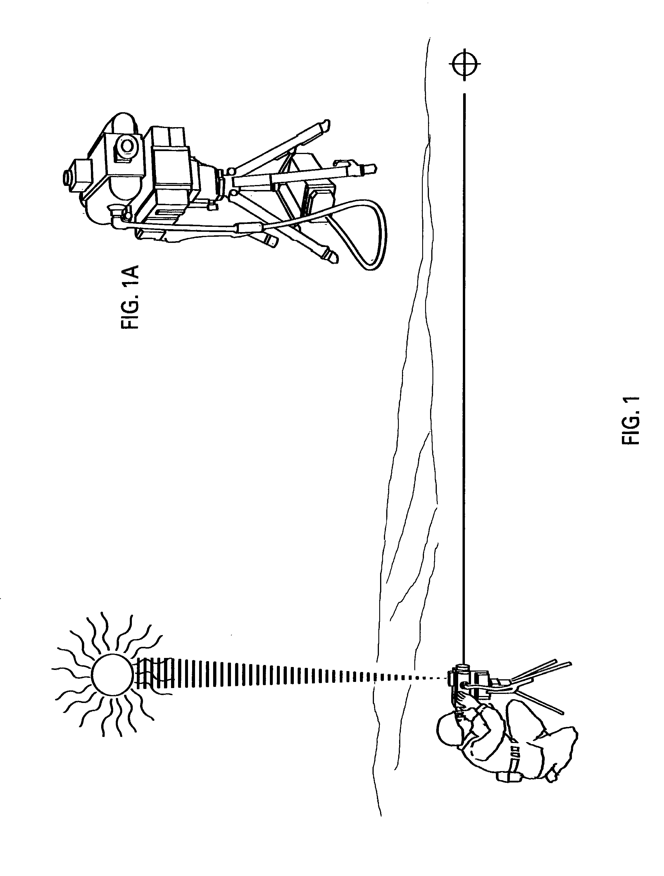
[0036]Preferred embodiments of the present invention can be described by reference to the drawings. A preferred embodiment is shown in FIG. 1 and FIG. 1A where the celestial compass 82 of the present invention is an accessory to a far target location system 84 mounted on a tripod. The celestial compass has imaged the sun 88 and with information from an inclinometer (not shown), the correct date and time and the correct geographic position of the laser finder, the processor within the celestial compass has determined the orientation of a telescope in the far target location system and with the timing of a return infrared laser pulse from target 90 has determined the exact geographic position of the target.

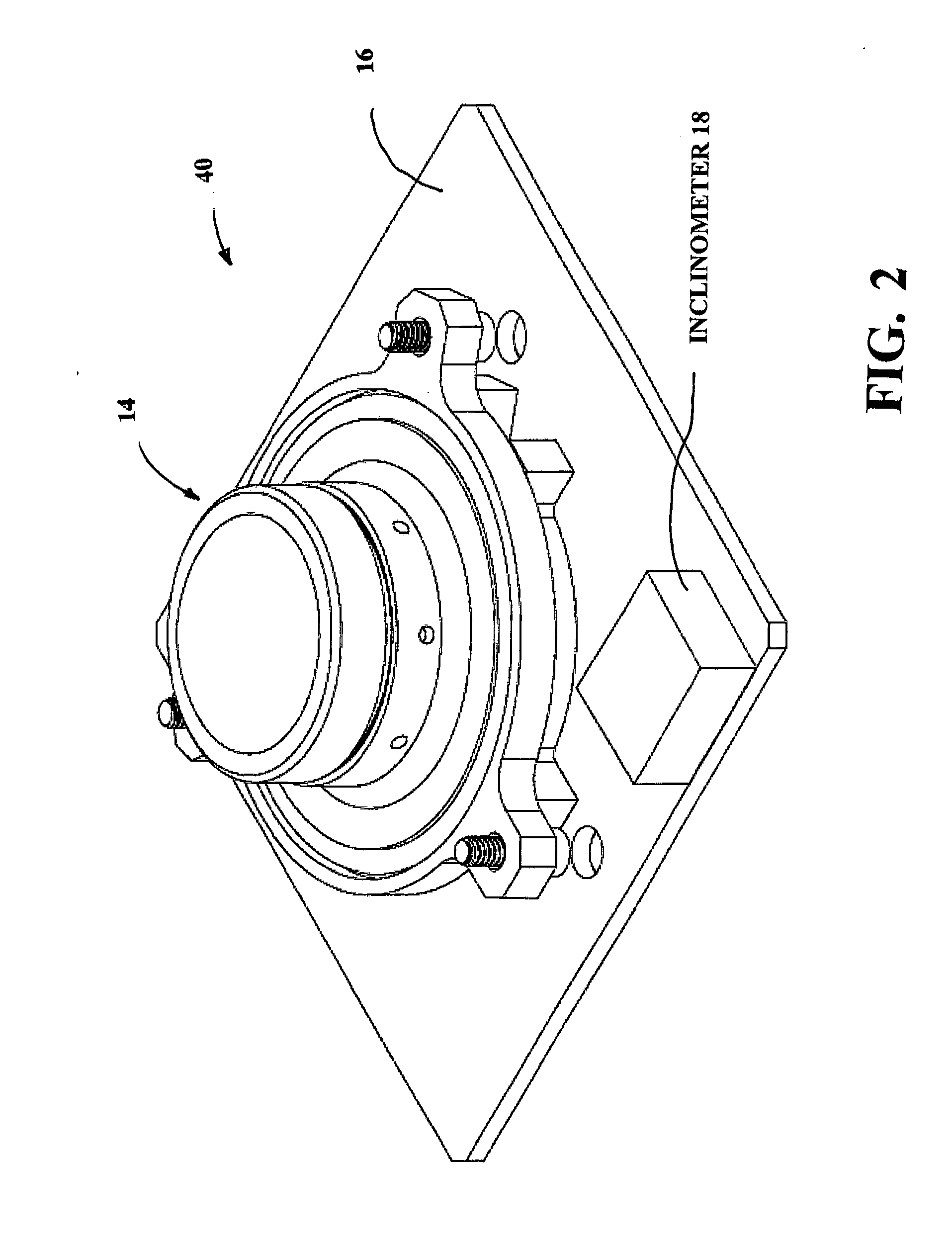
[0037]A preferred module of the celestial compass 82 of the present invention is shown in detail in FIGS. 2 through 8. FIG. 2 is a prospective view of the celestial compass. Shown in the drawing is celestial compass 82, with a single fisheye lens assembly 14 mounted on circuit board...


PUM


Abstract

A celestial compass kit. The kit includes an inclinometer, a camera system with a special telecentric fisheye lens for imaging at least one celestial object and a processor programmed with a celestial catalog providing known positions at specific times of at least one celestial object and algorithms for automatically calculating target direction information based on the inclination of the system as measured by the inclinometer and the known positions of at least one celestial object as provided by the celestial catalog and as imaged by the camera. The telecentric fisheye lens produces an image on the sensor located at or near the focal plane which remains spatially constant within sub-micron accuracies despite thermally produced changes in the focus of the lens.

Description

CROSS REFERENCE TO RELATED APPLICATIONS[0001]This application is a continuation in part of patent application Ser. No. 12 / 283,785, Portable Celestial Compass filed Sep. 15, 2008, Ser. No. 12 / 319,651, Angles Only Navigation System filed Jan. 8, 2008 and Ser. No. 12 / 583,776 Miniature Celestial Direction Detector filed Aug. 25, 2009 and Ser. No. 12 / 586,813 filed Sep. 28, 2009, each of which are incorporated herein by reference.FEDERAL SUPPORTED RESEARCH[0002]The present invention was made in the course of work under contract number W15P7T-06-D-E402 / 0091 and the United States Government had rights in the invention.FIELD OF INVENTION[0003]The present invention relates to direction detection systems, especially to such systems designed for use in determination of precise locations of targets.BACKGROUND OF THE INVENTIONSky Charts[0004]The position of celestial objects at any time at any place on earth is known with extremely high accuracy. These celestial objects include all recognizable s...

Claims


Application Information

Patent Timeline
IPC IPC(8): G01C21/02H04N7/00
CPCG01C17/34G01C21/02
Inventor BELENKII, MIKHAILBARRETT, TODDBRINKLEY, TIMOTHY
Owner TREX ENTERPRISEES
Why Eureka
Try Eureka