Optical device

a technology of optical devices and lenses, applied in the field of optical devices, can solve the problems of inadvertently large number of processes required to select and incorporate desired ones, decentering the lens, and significant increase in manufacturing costs, and achieve the effect of easy fine adjustmen

Inactive Publication Date: 2006-01-05
TAMRON
View PDF1 Cites 8 Cited by
  • Summary
  • Abstract
  • Description
  • Claims
  • Application Information

AI Technical Summary

Benefits of technology

[0033] An optical device according to the present invention is easy to finely adjust at least part of t

Problems solved by technology

In such a configuration, even if the desired separating collar is selected from the separating collars as mentioned above and incorporated in the device, the number of the separating collars must be considerably large to resultantly cause a significant in

Method used


Image

  • Optical device
  • Optical device
  • Optical device

Examples


embodiment 1

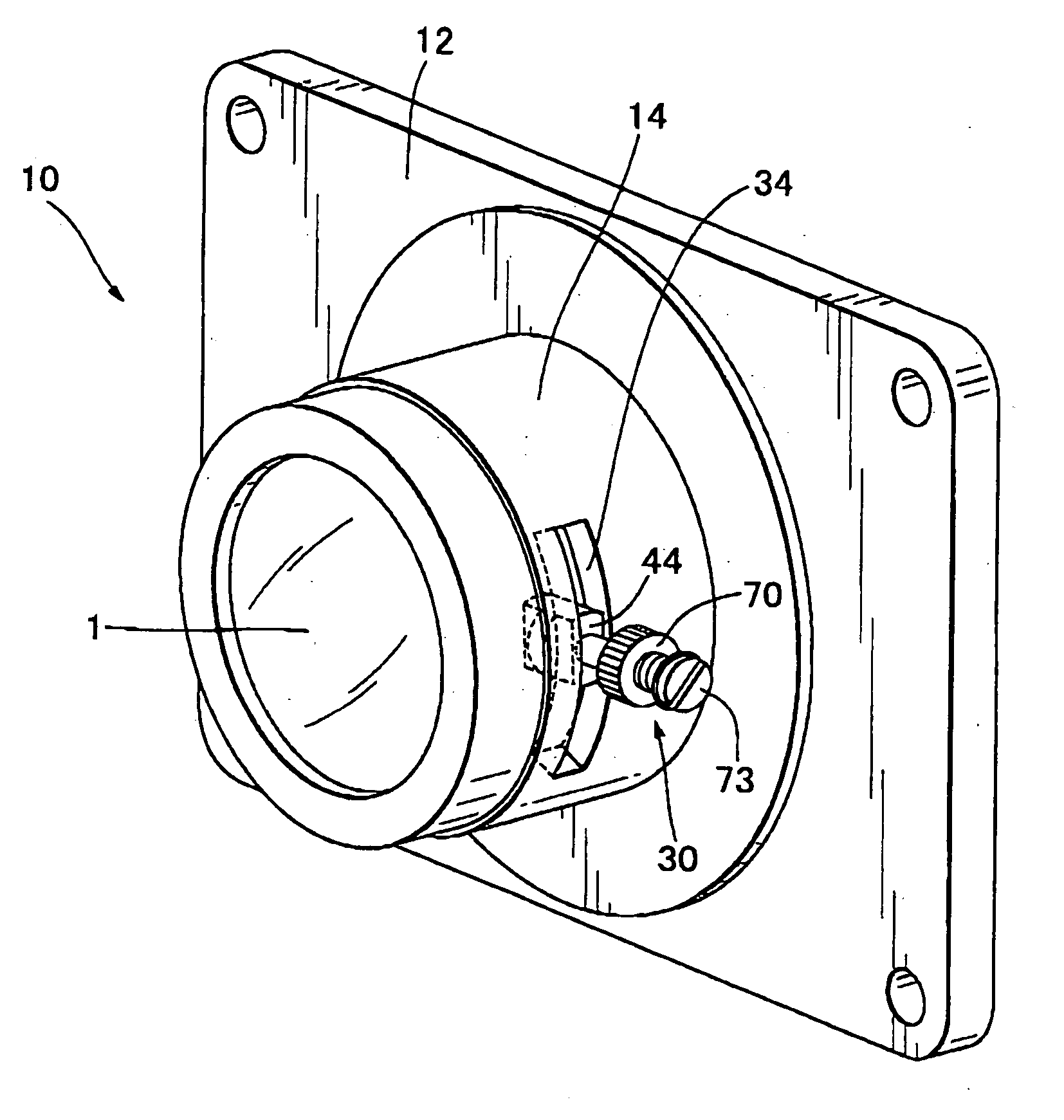
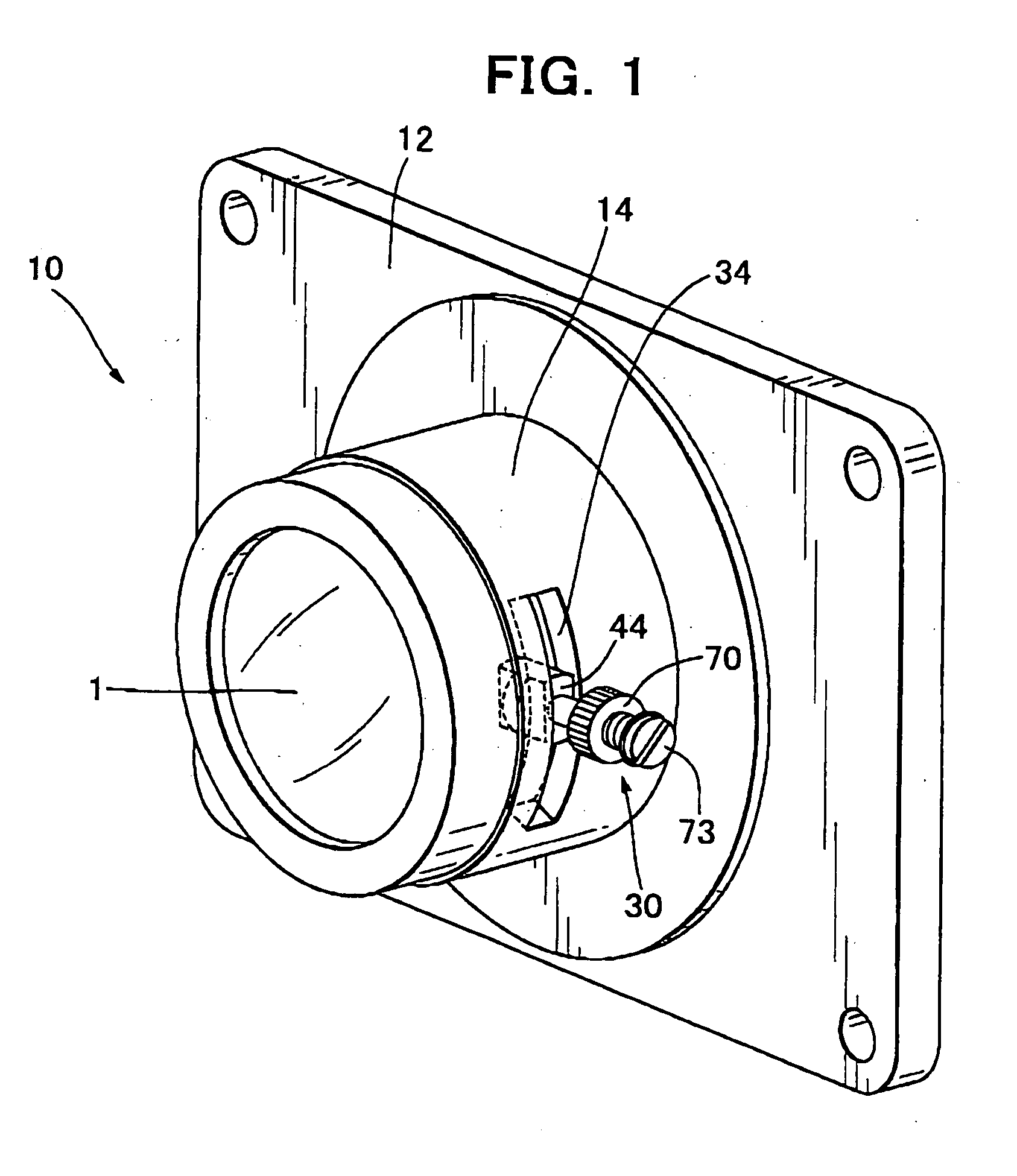
[0046] An optical device 10 in a first preferred embodiment is projection lens optics dedicated to a rear projection picture device such as a rear projection TV set, a rear projector and the like. The optical device 10 has, as shown in FIG. 1, an adapter flange 12 and a fixed lens barrel 14 integrally molded of synthetic resin.

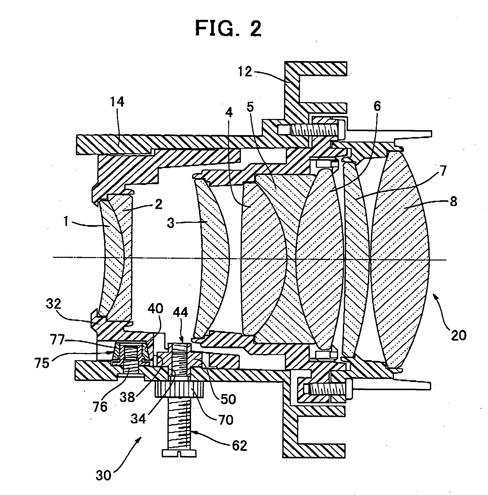
[0047] As can be seen in FIG. 2, the fixed lens barrel 14 houses an imaging lens 20 consisting of lenses 1 to 8. The lenses 3 to 8 are fixedly held in some well known manner. The lenses 1 and 2 are the ones which greatly affect an imaging performance and a focal length and are held by a lens position adjusting mechanism 30 so as to be able to adjust the lenses in position along the optical axis.

[0048] The lens position adjustment mechanism 30 has, as depicted in FIG. 2, a slidable lens frame 32 inside a distal end of the fixed lens barrel 14, namely, inside an end opposed to the adapter flange 12.

[0049] As can be seen in FIGS. 1 and 2, the fixed lens barrel...

embodiment 2

[0057] A second preferred embodiment of the present invention, is an optical device 110, as depicted in FIG. 5 where like reverence numerals denote the similar components to those of the optical device 10 of the first embodiment, and the descriptions of the components are omitted. The optical device 110 of the second preferred embodiment of the present invention has a slidable lens barrel 114 with a cam groove 112 in an inclined surface relative to the plane orthogonal to the optical axis. The slidable lens barrel 114, which frictionally slides on an inner surface of the fixed lens barrel 14, holds the lenses 1 and 2.

[0058] The slidable lens barrel 114 is provided with a circular hole 120. A positioning stud 116 is fitted in the circular hole 120 and frictionally slid therein in the circumferential directions about the optical axis. The positioning stud 116 is, as shown in FIGS. 6 and 7, comprised of a pillar member 122 slidably fitted in the circular hole 120 and flat projection m...


PUM


Abstract

An optical device according to the present invention is easy to finely adjust at least part of the lens optics and stable to secure the fine adjustment without decentering the part of the lens optics. The optical device includes a fixed lens barrel and a lens frame capable of sliding linearly along the optical axis and circumferentially about the same in relation with the fixed lens barrel where the fixed lens barrel and the slidable lens frame are mated with each other in cam engagement, and the fixed lens barrel is rotated relative to the slidable lens frame so as to move the slidable lens frame. While a fixing screw is fitted in the slidable lens frame, two elements engaged with the fixing screw pinch the fixed lens barrel between them so that the fixing screw is secured to the fixed lens barrel and that the slidable lens frame is secured to the fixed lens barrel.

Description

FIELD OF THE INVENTION [0001] The present invention relates to an optical device, such as a rear projection picture device like a rear projection TV set and a rear projector, and a high resolution monitor camera, which project light beam from behind of the screen to display an enlarged image thereon, and more particularly, it relates to an optical device that requires to retain highly accurate optical adjustability and enhanced optical stability of lens optics. BACKGROUND ART [0002] In the context of the rear projector, there are provided a lower cabinet that houses an image formation unit, and a primary body of screen, and an image displayed on a liquid crystal image display device in the image formation unit is projected from behind the screen to produce an enlarged image (i.e., a magnified picture) thereon (see Patent Document 1 listed below). [0003] The prior art rear projection picture device consists of upper and lower cabinets and is structured to project light beam from behi...

Claims


Application Information

Patent Timeline
IPC IPC(8): G02B7/02
CPCG02B7/023
Inventor ITOHIYA, TAKASHI
Owner TAMRON
Why Eureka
Try Eureka