Extruder

a technology of extruder and material, applied in the field of extruder, can solve the problem of insufficient devolatilization of materials, and achieve the effect of efficient devolatilization operation

Active Publication Date: 2006-01-05
KOBE STEEL LTD
View PDF9 Cites 32 Cited by
  • Summary
  • Abstract
  • Description
  • Claims
  • Application Information

AI Technical Summary

Benefits of technology

[0011] Accordingly, it is an object of the present invention to provide an extruder that can perform an efficient devolatilization operation on a material.

Problems solved by technology

This is problematic in that there are cases where the material is not sufficiently devolatilized.

Method used


Image

  • Extruder
  • Extruder
  • Extruder

Examples


first embodiment

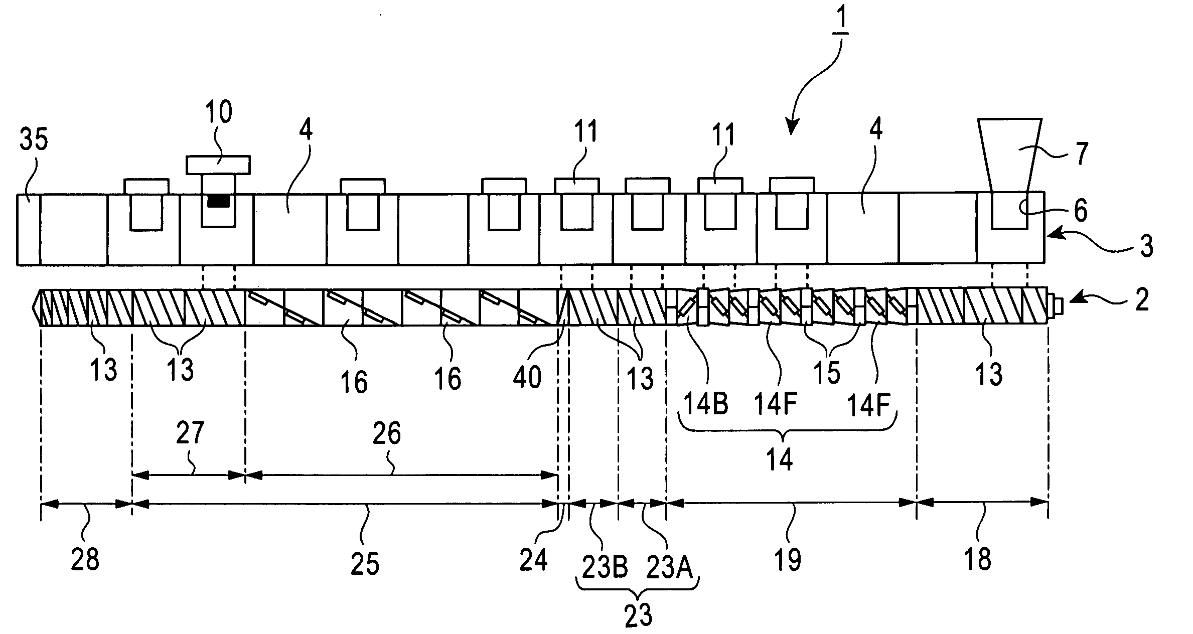
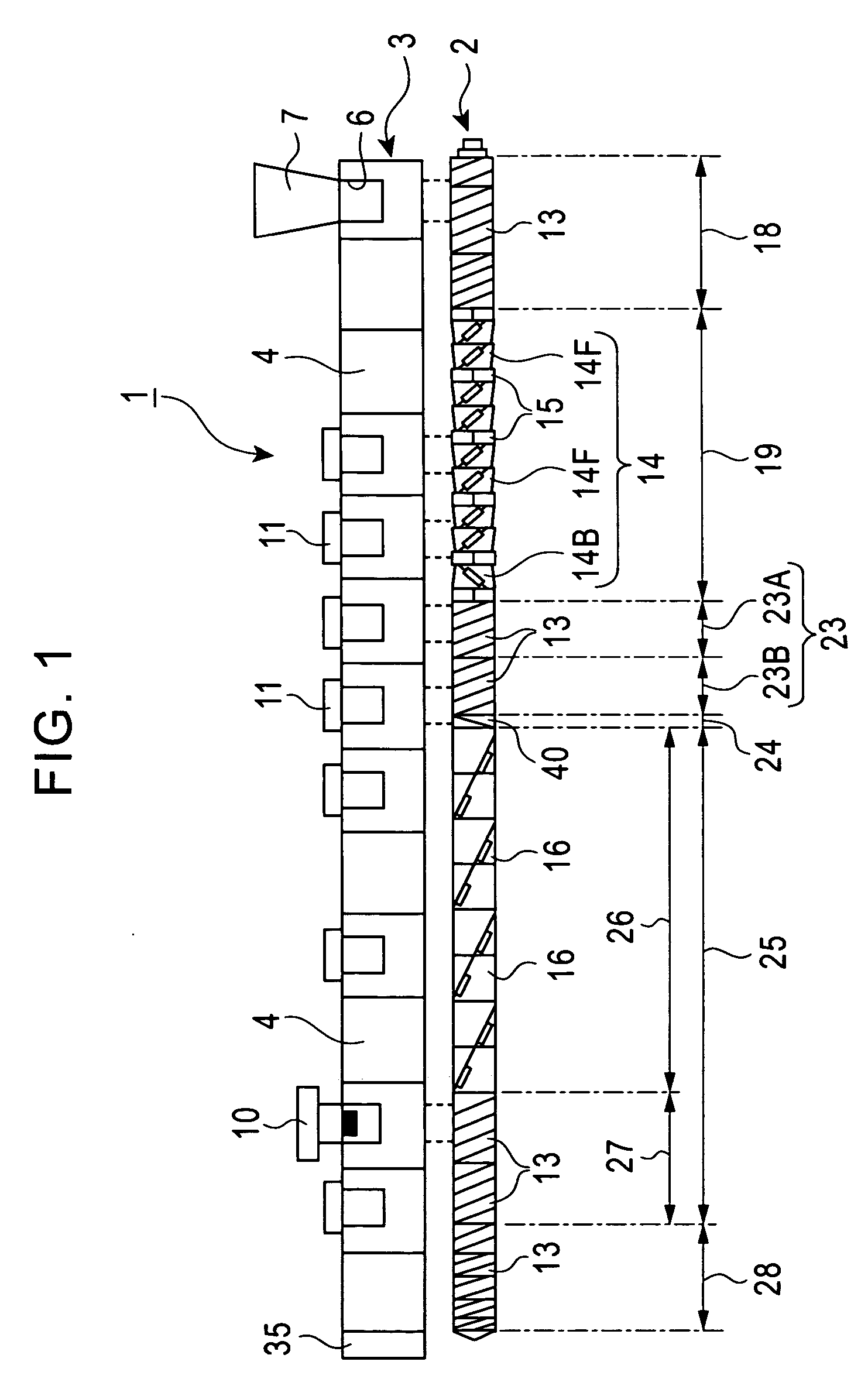
[0102] Referring to the twin screw extruder 1 according to the first embodiment, an example of an actual kneading operation of the material 8 will be described below.

[0103] The material 8 is composed of polyethylene resin, and is subject to devolatilization in the devolatilization portions 25 in order to remove the ethyl benzene and styrene monomer contained in the material 8. First, the polyethylene resin is plasticized and melted in the first kneading sections 19. Subsequently, in the devolatilization portions 25, while the polyethylene resin is transferred downstream, the volatile components, i.e. the ethyl benzene and styrene monomer, are vaporized and sucked into the vacuum vent 10 using a vacuum pump so as to be released outward from the barrel.

[0104] The overall length of each kneading screw 2 is L / D=50. The length of each devolatilization portion 25 is L / D=16. The diameter of each kneading screw 2 is 46 mm. The rotating speed of each kneading screw 2 is set at 400 rpm. The...

second embodiment

[0106] The following is an example in which the material 8 is composed of polyethylene resin, and a compound mixed with carbon black is manufactured using the extruder 1 according to the second embodiment. Here, the diameter of each kneading screw 2 is 46 mm and the overall length thereof is L / D=54.

[0107] Each of the first kneading sections 19 includes the rotor segments 14 and the kneading disc segments 15 (having three kneading discs disposed at a phase angle of 45° with respect to each other), and performs a kneading process and dispersing and mixing processes of the carbon black with respect to the polyethylene resin.

[0108] The amount of extrusion of the material 8 is set at 150 kg / h. The rotating speed of each kneading screw 2 is set at 400 rpm. The temperature of the kneaded material 8 is set at 228° C. Under these conditions, the kneading operation was performed. As a result, the percentage content of styrene monomer was 0.001% or less, meaning that a compound having a low ...


PUM

PropertyMeasurementUnit
twist angleaaaaaaaaaa

Abstract

An extruder includes a barrel and a kneading screw extending through the barrel in a rotatable fashion. The kneading screw is provided with a devolatilization portion. The devolatilization portion includes a kneading flight that is twisted in a direction for transferring a material downstream. The kneading flight kneads the material while transferring the material downstream and separates a volatile component from the material. Impregnation sections, which allow the kneading chamber to be impregnated with the material, are respectively disposed adjacent to an upstream side and a downstream side of the devolatilization portion so that the air-tightness of the devolatilization portion of the extruder is maintained. Accordingly, an efficient devolatilization operation of the material is achieved.

Description

BACKGROUND OF THE INVENTION [0001] 1. Field of the Invention [0002] The present invention relates to an extruder suitably used for devolatilizing a material, such as plastic and rubber, in order to efficiently remove volatile components contained in the material. [0003] 2. Description of the Related Art [0004] Generally, a composite resin material, such as a plastic compound, is manufactured by injecting a polymeric resin material and a powdery additive into a barrel of a continuous kneading unit, and then extruding the two downstream while they are kneaded with a kneading screw extending through the barrel. Furthermore, a granulator, for example, is disposed adjacent to the downstream side of the continuous kneading unit, such that the granulator forms the composite resin material into pellets. [0005] A typical continuous kneading unit may either be a single kneading-screw type or a twin kneading-screw type. [0006] A twin-screw continuous kneading unit includes a barrel having ther...

Claims


Application Information

Patent Timeline
Patent Type & Authority Applications(United States)
IPC IPC(8): B29C47/40B29C48/04B29C48/395B29C48/76
CPCB29C47/0011B29C47/767B29C47/402B29C47/38B29C48/04B29C48/395B29C48/402B29C48/767B29B7/7495B29B7/845B29B7/489
Inventor INOUE, KIMIOKASAI, SHIGEHIROFUNAHASHI, HIDEOFUJISAWA, KAZUHISANAKANISHI, HIRONOBU
Owner KOBE STEEL LTD
Why Eureka
Try Eureka