

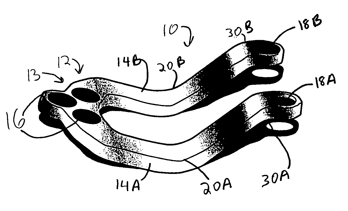
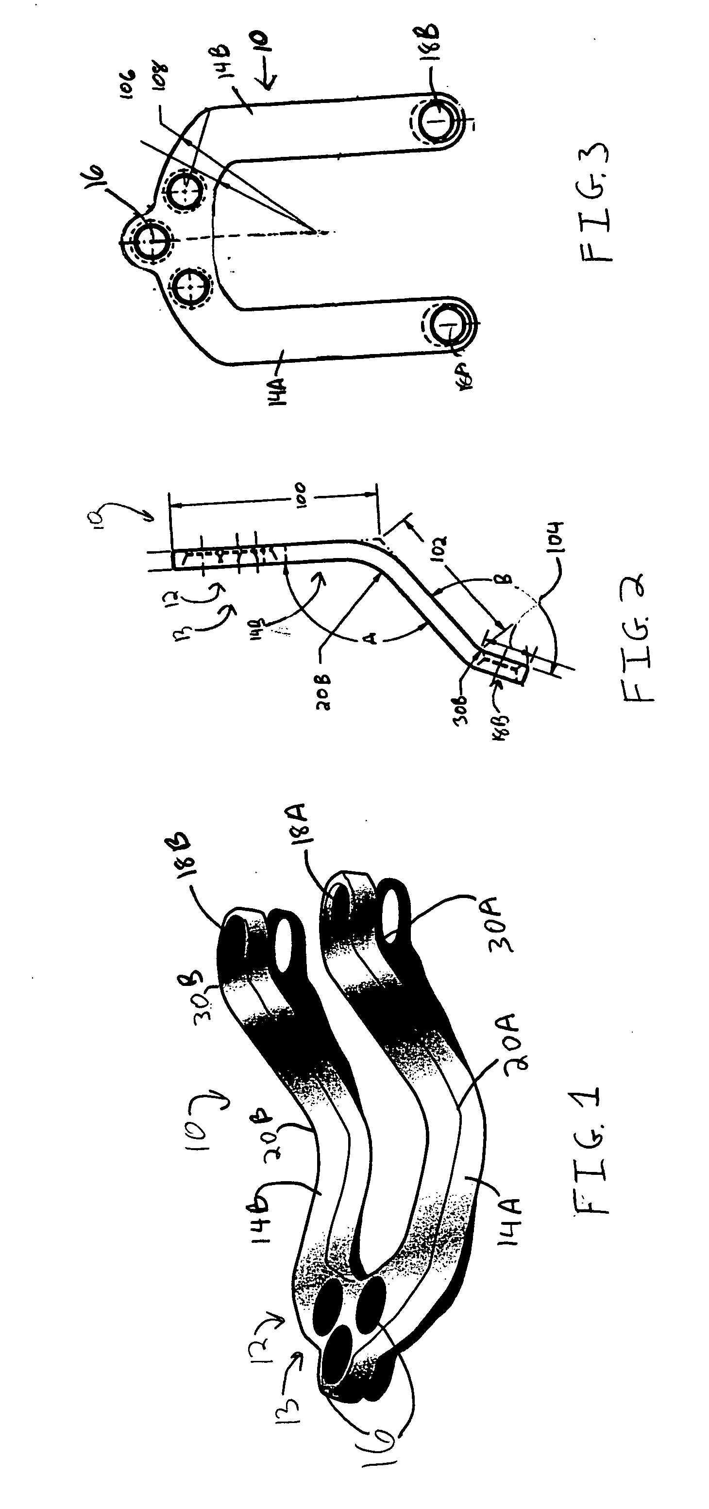
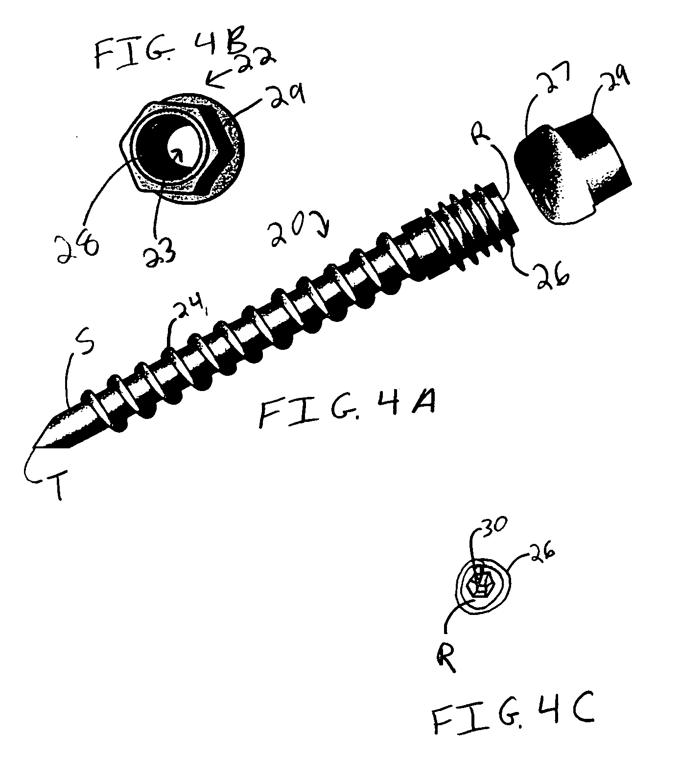
Occipitocervical plate
a technology applied in the field of occipital and cervical spine, can solve the problems of affecting the implantation procedure, prolonging and complicating the implantation procedure, and affecting the implantation effect,
- Summary
- Abstract
- Description
- Claims
- Application Information
AI Technical Summary
Benefits of technology
Problems solved by technology
Method used
Image

Examples
examples
[0045] Data used in this example was also used in preparing the paper, Gluf and Brockmeyer, Atlantoaxial transarticular screw fixation: a review of surgical indications, fusion rate, complications, and lessons learned in 67 pediatric patients, J. Neurosurg Spine 2:164-169, 2005, the disclosure of which is incorporated herein by reference.
[0046] 23 pediatric patients were treated for occipital cervical instability by occipitocervical fusion performed with implants in conjunction with C1-C2 transarticular screws. While older patients were treated using Ohio Medical Instruments U-loop, rod / plate devices, patients from the ages of 2 to 5 years of age were treated using a system in accordance with the present invention, referred to as the Avery Brockmeyer-Thiokol plate, sized to fit patients 2 to 5 years of age.
[0047] A preoperative imaging protocol including plain cervical flexion-extension radiography and thin-cut (1-mm) CT scanning of the occiput-C3 region with sagittal and coronal ...
PUM
 Abstract
Description
Claims
Application Information