
Modular fluid distribution system

a module-based, fluid-displacement technology, applied in the direction of pipeline systems, transportation and packaging, mechanical equipment, etc., can solve the problems of high processing requirements of chemical delivery systems, high labor intensity of assembly of these components, and high labor intensity of disassembly of these components for repair or replacemen

Inactive Publication Date: 2006-01-12
DOYLE MICHAEL
View PDF16 Cites 22 Cited by
  • Summary
  • Abstract
  • Description
  • Claims
  • Application Information

AI Technical Summary

Benefits of technology

[0015] The present invention is designed to provide a system for enabling the conditioning, control and distribution of fluids such as semiconductor processing gases and to provide an improved surface mount gas delivery system that does not make use of seals between blocks and requires only a single plane of interconnecting blocks.
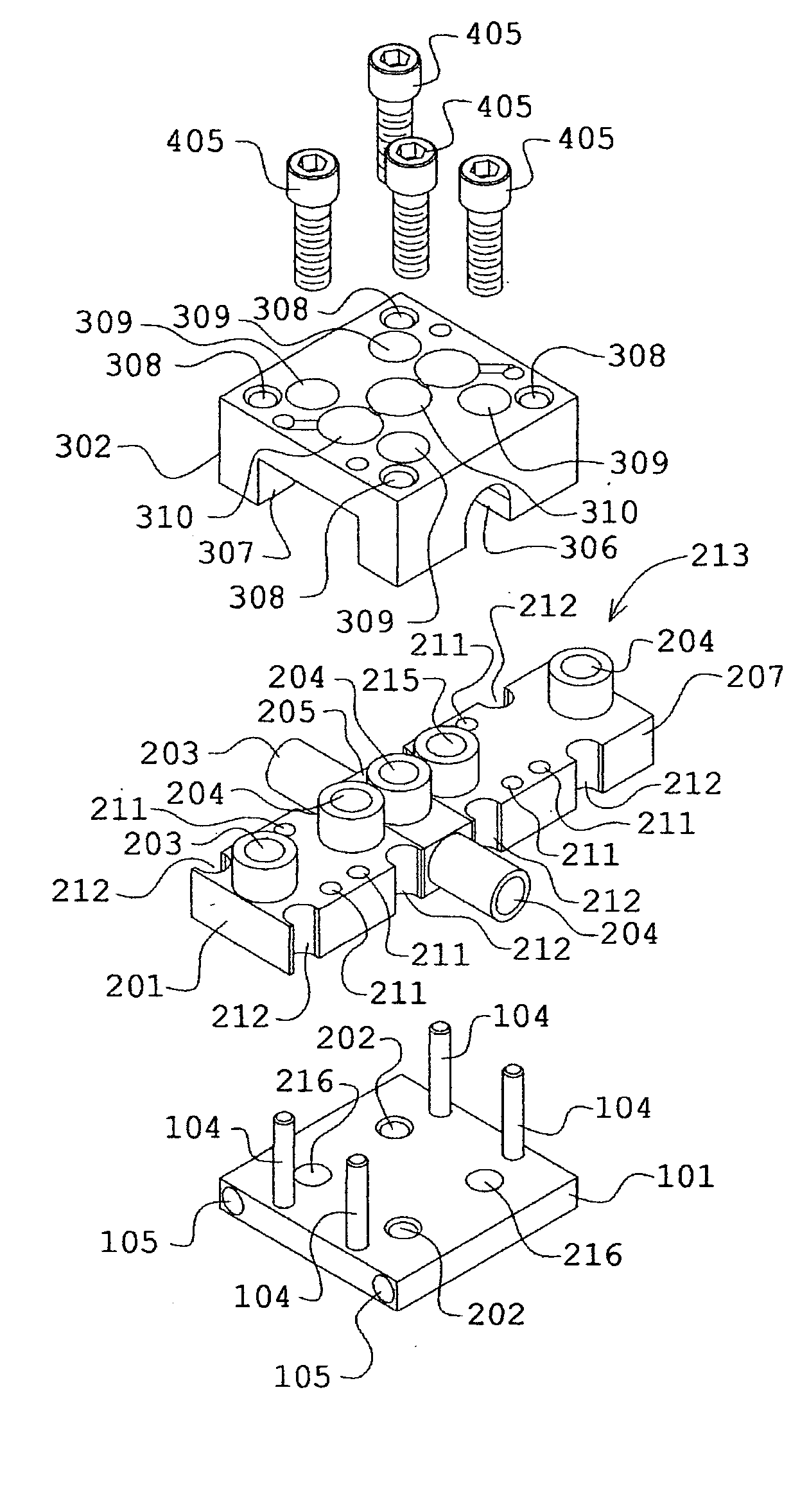
[0017] Base plates have threaded holes as well as guiding pins for precisely mounting and aligning fluid path blocks on one surface. A plurality of fluid path blocks, mounted on base plates and fastened together with component mounting blocks, form pathways arranged so that they receive gas, fluid, or vapor at an inlet and can pass the fluid along to a plurality of component receiving stations having an inlet and an outlet, with the fluid ultimately being delivered to the semiconductor manufacturing equipment.
[0020] Aligned thru-holes are provided on component mounting blocks and base plates to allow fastening of the distribution system to a structural plate to provide the rigidity necessary for handling, packaging and transporting as well as mounting inside the semiconductor-manufacturing equipment.

Problems solved by technology

Such processing often makes demanding requirements of chemical delivery systems.
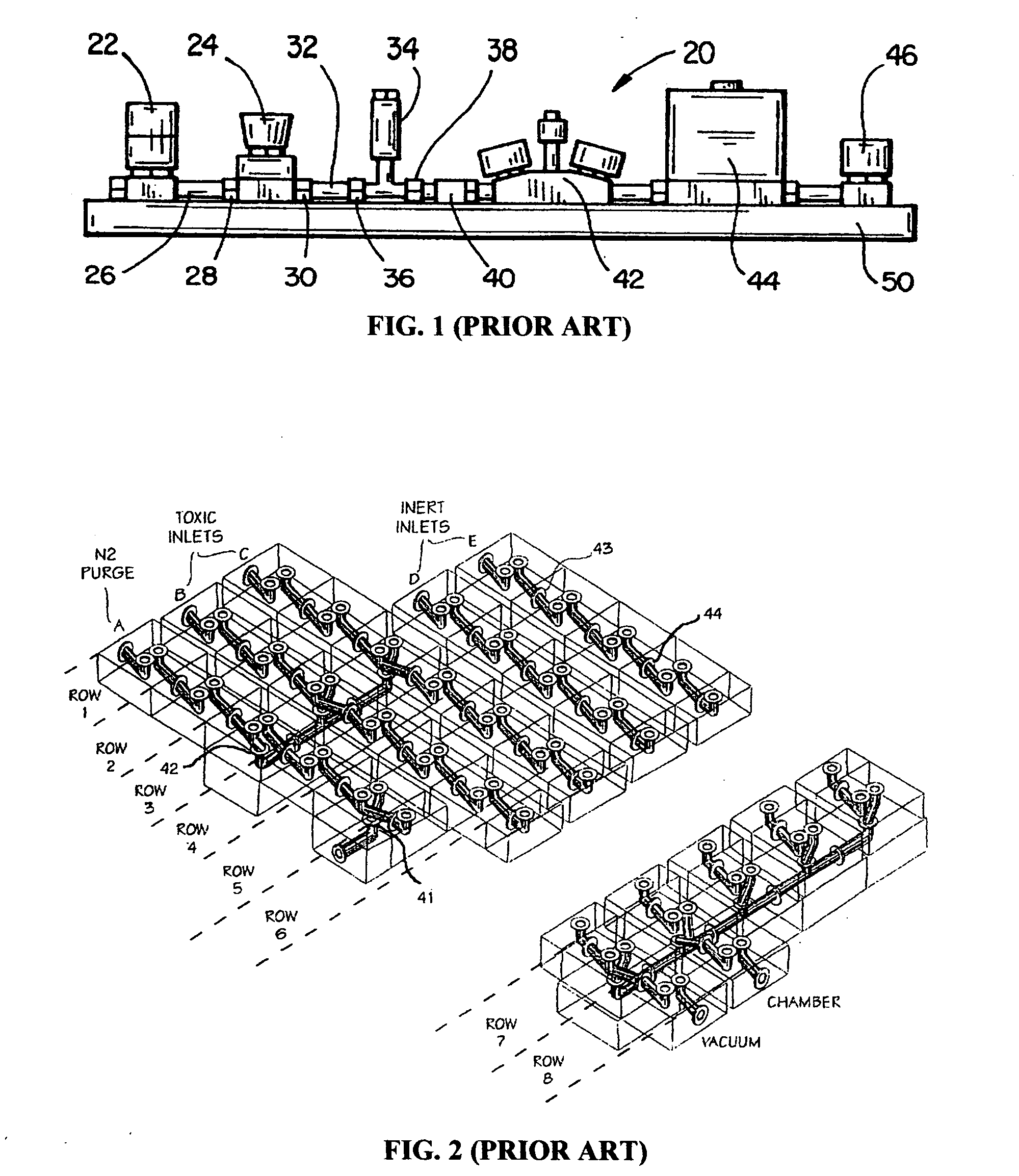
Those skilled in the art recognize a number of problems associated with prior art gas sticks of the type illustrated in FIG. 1.
The assembly of these components can be relatively labor intensive.
Similarly, the disassembly of these components for repair or replacement can be extremely labor-intensive.
Another problem associated with gas stick (20) is that the numerous fittings and pipe sections produce a relatively long and heavy device.
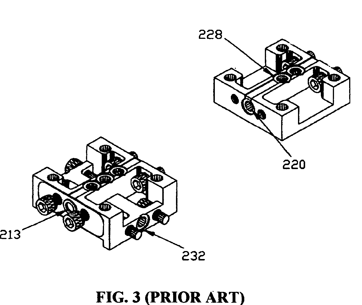
Interconnections between blocks or between sticks invariably include seals from block to block which result in additional complexity and accompanying degradation of system reliability.
Additionally, sealing integrity is compromised in some cases by placing two or more seals between blocks to be compressed in series.
The problem being that the degree of compression of the seals cannot be guaranteed to be equal at each junction; since a single joining force is applied to all seals in series and simultaneously.
Furthermore, it is common for entire gas sticks to become contaminated or corroded necessitating their replacement, as is the case, for example, in semiconductor fabrication processes that use SiH4 in its gaseous state.

Method used


Image

  • Modular fluid distribution system
  • Modular fluid distribution system
  • Modular fluid distribution system

Examples


Embodiment Construction

[0032] The detailed description set forth below in connection with the appended drawings is intended as a description of presently-preferred embodiments of the invention and is not intended to represent the only forms in which the present invention may be constructed and / or utilized. The description sets forth the functions and the sequence of steps for constructing and operating the invention in connection with the illustrated embodiments. However, it is to be understood that the same or equivalent functions and sequences may be accomplished by different embodiments that are also intended to be encompassed within the spirit and scope of the invention.

[0033]FIG. 4 is a perspective view of the building elements used in the invention. A modular fluid distribution system for use with fluid control components can be built using these building elements in accordance with an embodiment of the invention. The invention includes three major components: first base plate (101), first componen...


PUM


Abstract

A modular system for enabling a distribution of fluids, including a plurality of individual fluid path blocks that can be joined to substrate plates and component interfacing blocks to form gas sticks and gas panels. Each gas path block will have a fluid passageway with an entrance port and exit port accessing a common surface. Active components are mounted to the interfacing blocks, with each gas path block extending and interconnecting across immediately adjacent components in a stick or immediately adjacent sticks. Alignment features are provided to ensure that entrance and exit ports are accurately positioned to facilitate sealing.

Description

BACKGROUND [0001] 1. Field of Invention [0002] This invention relates generally to fluid control systems. Particularly, this invention relates to a modular mounting system for chemical fluid control components of a chemical fluid control system. [0003] 2. Description of Prior Art [0004] Fluid control components are used to control the delivery of a fluid (i.e., a gas or liquid) in industrial processes. Chemical delivery systems are used in numerous industries to control the flow of fluids, including gas reactants and other chemicals (e.g., liquids). Fluid control components are used to condition and control the delivery of fluids. Usually, these components are arranged so that fluid is carried through each of the components. For example, in semiconductor processing equipment, a variety of fluid control components are configured in a gas stick, which precisely controls the delivery of various fluids during semiconductor processing. In semiconductor processing, these systems are commo...

Claims


Application Information

Patent Timeline
IPC IPC(8): F17D1/00
CPCF17D1/04Y10T137/87885
Inventor DOYLE, MICHAEL
Owner DOYLE MICHAEL
Learn More