Fixing structure for a head lamp module of an automobile

a technology for fixing structures and head lamps, which is applied in vehicle interior lighting, transportation and packaging, and light and heating equipment, etc. it can solve the problems of increasing the repair cost and time, frequent damage, and the inability to achieve rapid repair of the head lamp module, so as to facilitate the initial assembly of the head lamp. , the effect of quick and easy repair

Active Publication Date: 2006-01-12
HYUNDAI MOBIS CO LTD
View PDF5 Cites 21 Cited by
  • Summary
  • Abstract
  • Description
  • Claims
  • Application Information

AI Technical Summary

Benefits of technology

[0013] Therefore, the present invention has been made in view of the above problems, and it is an object of the present invention to provide a fixing suture for a head lamp module of an automobile, which allows the head lamp module to be simply separated from an automobile carrier without requiring disassembly of a bumper mounted on the carrier, thereby enabling rapid and easy repair of a head lamp and facilitating initial assembly of the head lamp.

Problems solved by technology

In general, a head lamp selves as a light to illuminate a driver's visual field at night or when passing though a tunnel, and tends to be frequently damaged due to automobile crashes or other environmental factors.
Separation of other associated elements, such as a bumper, causes an increase in repair costs and time.
In the conventional fixing slue of the head lamp module as mentioned above, however, the bumper must be first separated from the head lamp module in order to exchange the head lamp module, thus making it impossible to achieve rapid repair of the head lamp module.

Method used


Image

  • Fixing structure for a head lamp module of an automobile
  • Fixing structure for a head lamp module of an automobile
  • Fixing structure for a head lamp module of an automobile

Examples


Embodiment Construction

[0024] Now, preferred embodiments of the present invention will be explained with reference to the accompanying drawings.

[0025] It is to be understood that the following detailed description related to the embodiments of the present invention are exemplary and explanatory only and not restrictive of the invention, and the present invention can be implemented in numerous ways.

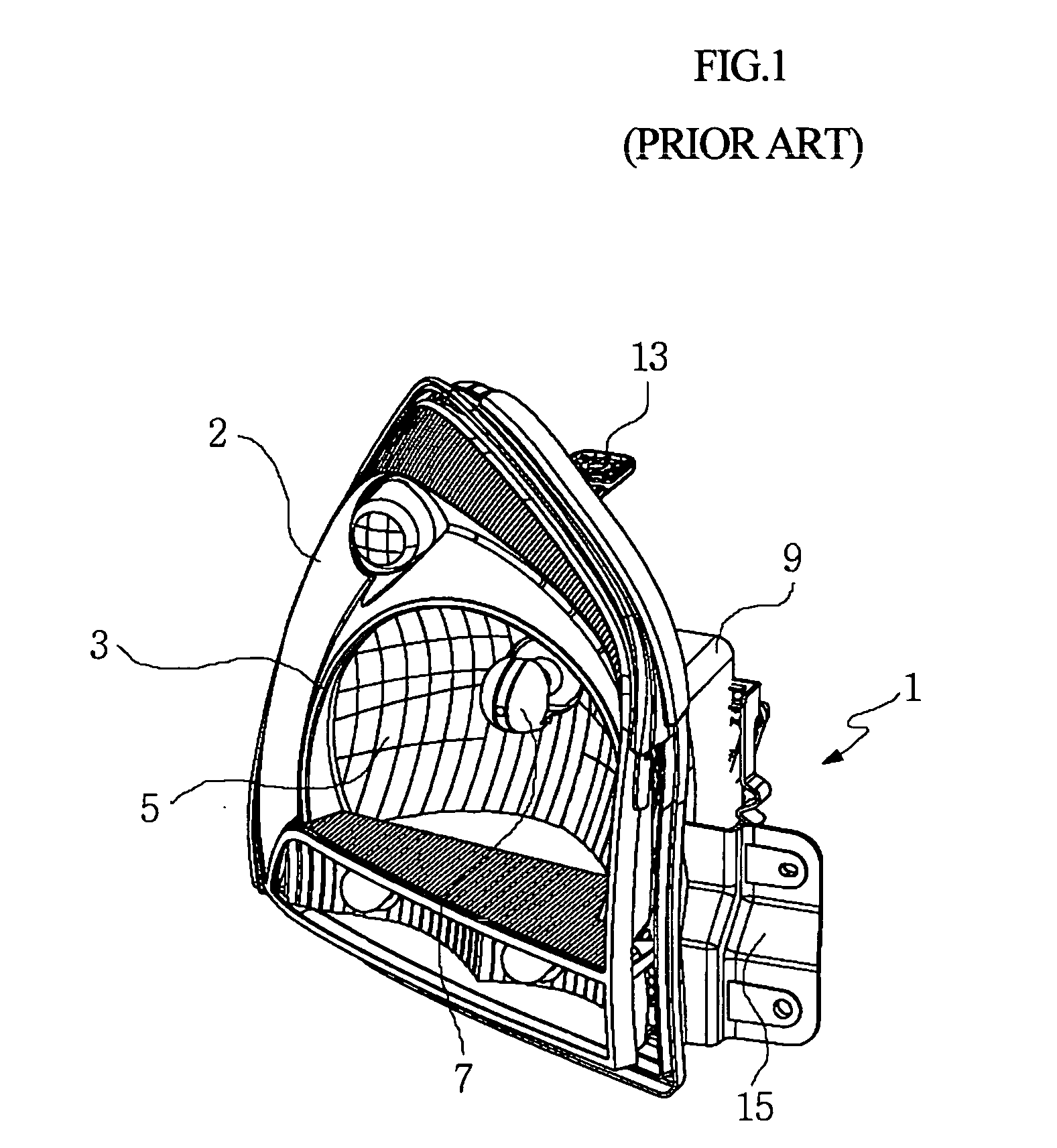
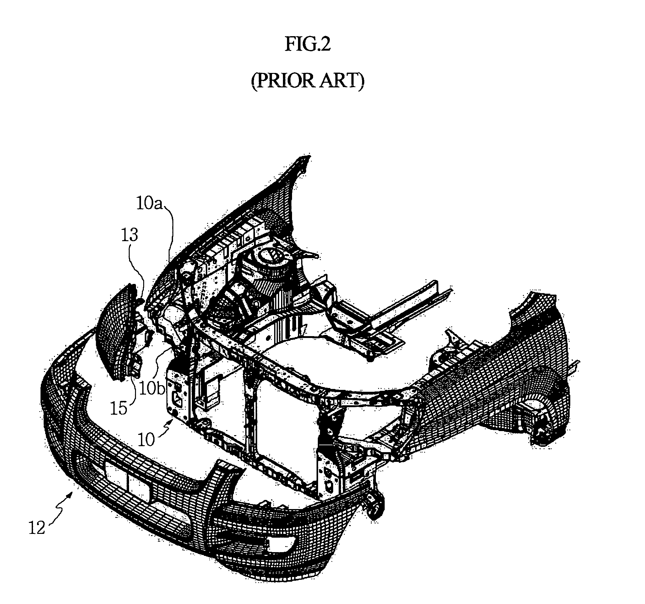
[0026]FIG. 4 is an exploded perspective view illustrating a fixing structure for a head lamp module of an automobile according to an embodiment of the present invention. FIG. 5 is an exploded perspective view of the fixing structure for the head lamp module, as seen from the opposite direction of FIG. 4. FIG. 6 is a perspective view illustrating an assembled state of the fixing structure for the head lamp module. FIG. 7 is a perspective view illustrating loops, a bracket, and a clip constituting the fixing structure for the head lamp module. FIG. 8 is a rear sectional view of the fixing structure for the head ...


PUM


Abstract

A fixing structure for a head lamp module of an automobile comprises the head lamp module, a bracket, and a clip. The head lamp module, configured to be coupled to the font surface of a carrier of the automobile, has a fixing panel piece integrally formed at an upper position thereof to be fixed at the carrier, and a pair of rearward-protruding semi-circular loops defining fitting bores, respectively. The bracket has a pair of rectangular holes which allow the loops of the head lamp module to pass there through, so as to position the fitting bores in front of the bracket, and a pair of bolt holes, which allow the bracket to be bolted to the front surface of the carrier. The clip is configured to be inserted downward through the fitting bores of the loops passed though the holes of the bracket, so as to allow the head lamp module to be mounted to the front surface of the carrier via the bracket.

Description

RELATED APPLICATIONS [0001] The present disclosure relates to subject matter contained in Korean Application No. 10-2004-0064751, filed on Aug. 17, 2004, which is herein expressly incorporated by reference its entirety. BACKGROUND OF THE INVENTION [0002] 1. Field of the Invention [0003] The present invention relates to a fixing structure for a head lamp module of an automobile, and more particularly to a fixing structure for a head lamp module of an automobile in which the head lamp module is coupled to a bracket of a carrier by means of a clip, thereby being capable of achieving simple attachment / detachment of the head lamp module relative to the carrier of the automobile without requiring disassembly of a bumper. [0004] 2. Description of the Related Art [0005] In general, the body of an automobile, defining the a of the automobiles, is comprised of a passenger compartment, an engine room or trunk compartment, fender, and the like. Such an automobile body is divided into a front bo...

Claims


Application Information

Patent Timeline
Patent Type & Authority Applications(United States)
IPC IPC(8): F21V17/02
CPCB60Q1/0064B60Q1/0441B60Q1/0433B60Q1/04
Inventor KIM, MYEONG-KI
Owner HYUNDAI MOBIS CO LTD
Why Eureka
Try Eureka