
Methods for treating defects and injuries of an intervertebral disc

a technology of intervertebral discs and treatment methods, applied in the field of spine systems and methods, can solve the problems of uncontrolled leakage, affecting the treatment effect, and causing the potential for the prosthetic fluid to ooze or seep out of the disc spa

Inactive Publication Date: 2006-01-12
SPINEWAVE
View PDF71 Cites 96 Cited by
  • Summary
  • Abstract
  • Description
  • Claims
  • Application Information

AI Technical Summary

Benefits of technology

The patent text describes methods for treating damaged spinal discs by introducing a curable biomaterial into the intradiscal space between opposing vertebral bodies. The methods involve removing a portion of the nucleus pulposus to create an intradiscal space, applying a first distraction force on the opposing vertebral bodies from within the space, applying a second distraction force on the opposing vertebral bodies externally of the space, and introducing the biomaterial through the annulus access directly into the space. The methods may also involve determining the volume of the space and optimizing the distraction of the space. The technical effects of the patent text include improved methods for preparing the spinal disc for treatment and evaluation of the integrity of the space before filling it with the biomaterial.

Problems solved by technology

Problems associated with these devices occur during insertion, whereby the pressure required to fill the disc space can cause leakage of the material into sensitive adjacent areas.
Much of the prior art contemplates free injection of biomaterial into a spinal space which may lead to uncontrolled leakage.
Lastly, some methods require insertion under high pressure, thereby creating a potential for the prosthetic fluid to ooze or seep out of the disc space intra-operatively.

Method used


Image

  • Methods for treating defects and injuries of an intervertebral disc
  • Methods for treating defects and injuries of an intervertebral disc
  • Methods for treating defects and injuries of an intervertebral disc

Examples


Embodiment Construction

[0037] For the purposes of promoting an understanding of the principles of the invention, reference will now be made to the embodiments illustrated in the drawings and described in the following written specification. It is understood that no limitation to the scope of the invention is thereby intended. It is further understood that the present invention includes any alterations and modifications to the illustrated embodiments and includes further applications of the principles of the invention as would normally occur to one skilled in the art to which this invention pertains.

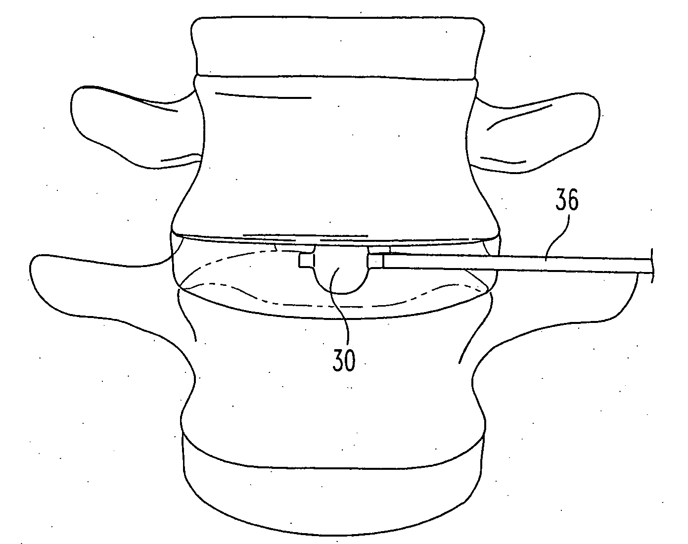
[0038] In one embodiment of the invention, adjacent vertebral bodies are distracted (by a non compliant balloon) at a predetermined pressure, such as at 200 psi (13 atmospheres). Using a non-compliant balloon restricts the lateral dimension of the balloon and ensures that there is no lateral loading, or pressurization of the annulus, thereby avoiding the risk of damaging the annulus. The balloon (and thereby t...


PUM


Abstract

A method for treating a herniated spinal disc between opposing vertebral bodies having a damaged outer annulus and an inner nucleus pulposus comprises the steps of: providing access to the nucleus pulposus through the annulus; removing at least a portion of the nucleus pulposus to create an intradiscal space; applying a first distraction force on the opposing vertebral bodies from within the intradiscal space; applying a second distraction force on the opposing vertebral bodies externally of the intradiscal space; and introducing a curable biomaterial through the annulus access directly into the intradiscal space. The first distraction force is applied within the disc space to distract the anterior aspect of the intradiscal space, while the second distraction force is applied exterior to the disc to act on the posterior aspect of the vertebral bodies. The first distraction force is applied prior to the application of the second distraction force and then removed. The second distraction force is maintained during the introduction of the biomaterial into the intradiscal space.

Description

REFERENCE TO RELATED APPLICATION [0001] The present application claims priority to co-pending provisional application No. 60 / 583,665, entitled “SYSTEMS AND METHODS FOR INJECTING A CURABLE BIOMATERIAL INTO AN INTERVERTEBRAL SPACE”, filed on Jun. 29, 2004, the entire disclosure of which is incorporated herein by reference.BACKGROUND OF THE INVENTION [0002] The present invention relates to systems and methods for the treatment of the spine, and especially the interbody disc space. More specifically, the invention concerns the injection of a biomaterial into a spinal space, such as the intradiscal space. [0003] Spine fusion procedures represent the state of the art treatment for intervertebral disc problems, which generally involve open surgery and the use of interbody fusion cages and spinal fixation systems to stabilize the fusion site. An alternative treatment under evaluation is to replace or augment the disc or nucleus pulposus with a prosthetic device. Examples of some devices cur...

Claims


Application Information

Patent Timeline
Patent Type & Authority Applications(United States)
IPC IPC(8): A61F2/46A61F2/44A61B17/88A61F2/958
CPCA61B17/70A61B17/8811A61B17/8827A61B2017/0256A61B2017/564A61M29/02A61F2/4657A61F2/4684A61F2002/444A61F2002/4627A61F2002/4663A61F2/4611
Inventor COLLINS, KEITHWILSON, THOMAS G.WALKENHORST, JAREDLEE, DENNISCARTER, ANDREWPAFFORD, JOHNLOGUIDICE, MARK D.MIDDLETON, LANCEBOYD, LAWRENCE
Owner SPINEWAVE
Learn More