Method and apparatus for anchoring of pacing leads

a technology of pacing leads and anchoring devices, applied in the field of cardiac surgery, can solve problems such as the inability to rotate the insertors

Inactive Publication Date: 2006-01-12
KURTH +1
View PDF3 Cites 50 Cited by
  • Summary
  • Abstract
  • Description
  • Claims
  • Application Information

AI Technical Summary

Benefits of technology

[0007] The invention is an introducer having a distal end comprising an anchor provided on the distal end of the introducer for attachment of the distal end of the introducer into tissue. The anchor attaches at or near the surface of a body cavity, for

Problems solved by technology

Being precurved, such introducers cannot be rotated for the purpose of setting a screw-in anchor into myocardium, since their distal ends wobble uncontrollably while being rotated.
If the pacemaker lead is not supported by a fixed-in-place introducer, the pacemaker lead itself can either pu

Method used


Image

  • Method and apparatus for anchoring of pacing leads
  • Method and apparatus for anchoring of pacing leads
  • Method and apparatus for anchoring of pacing leads

Examples


second embodiment

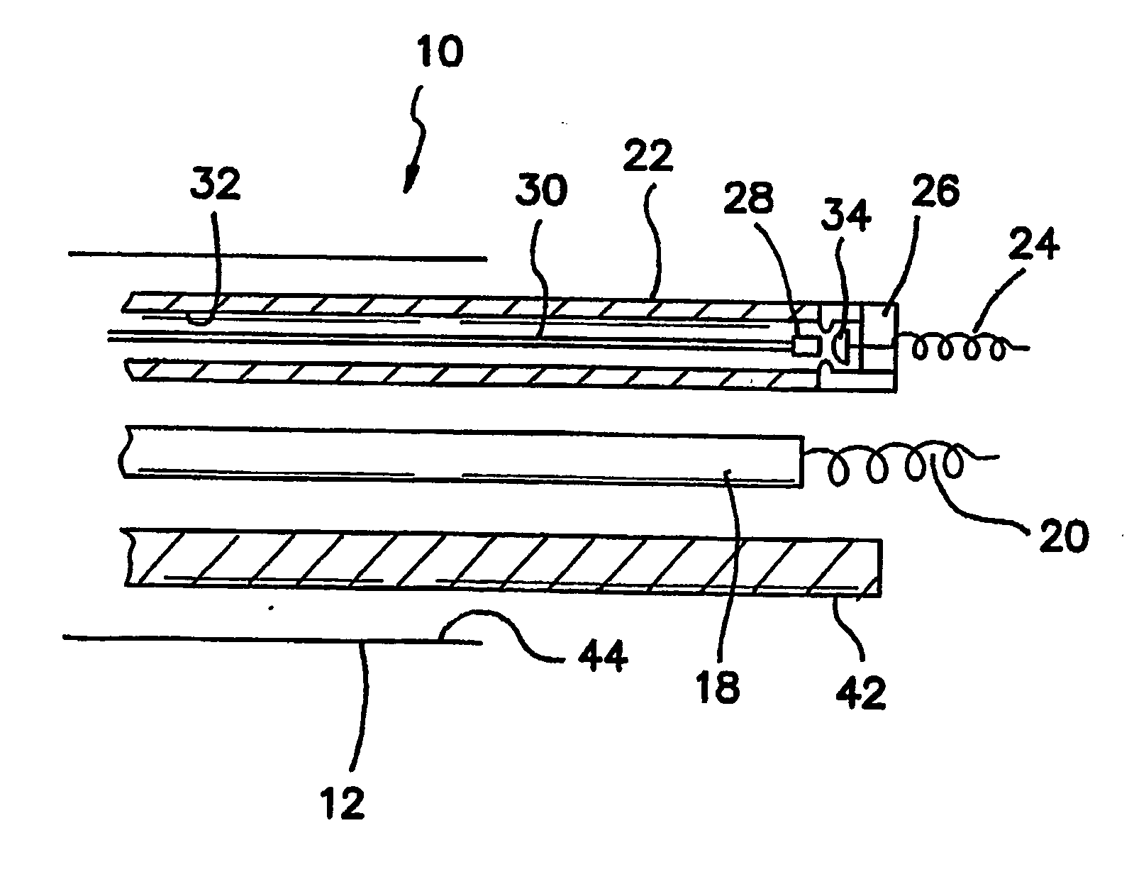
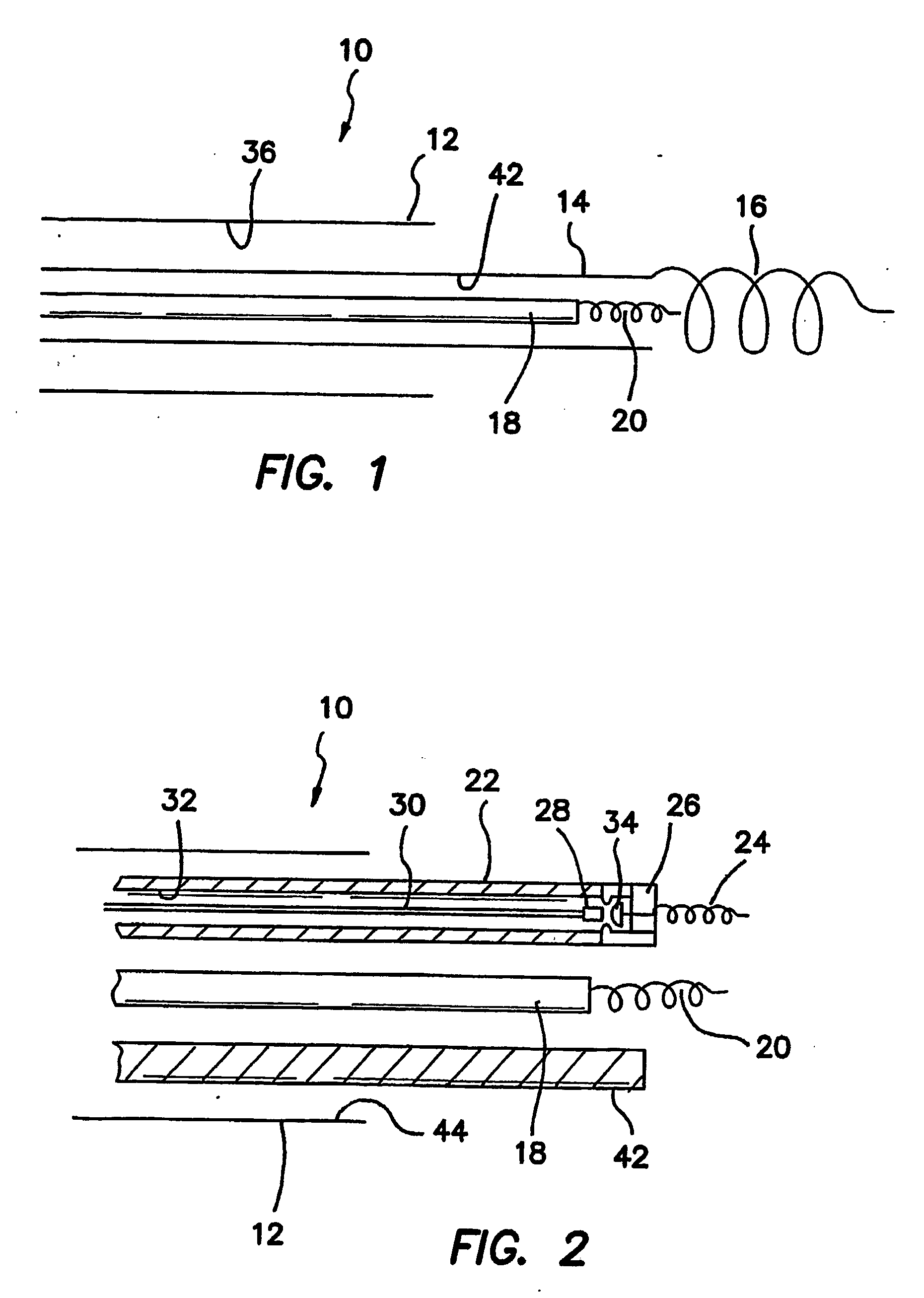
[0064]FIG. 2 is a side cross sectional view of the distal end of telescopic introducer 10 which is comprised of a biased introducer 22 through which pacemaker lead 18 with distal anchor 20 is implanted. A parallel lumen 32 is defined in the wall of introducer 22 through which a torsional wire 30 is disposed. Wire 30 has a termination 28 which is or can be coupled with a captive screw 34 which has a distal anchor 24. It is contemplated that screw 34 will be retained within lumen 32 until deployment, at which time it is then distally extended by being pushed by wire 30 and then rotated by wire 30 to fix anchor 24 into the adjacent myocardium. In this embodiment, anchors 20 and 24 are not telescopic, but are deployed in parallel.

[0065] It is to be understood that instead of a captive screw 34, wire 30 and anchor 24 may be integral and simply delivered through auxiliary lumen 32. A plurality of such auxiliary lumens 32 and wire 30 / anchor 24 combinations may be provided and employed in a...

third embodiment

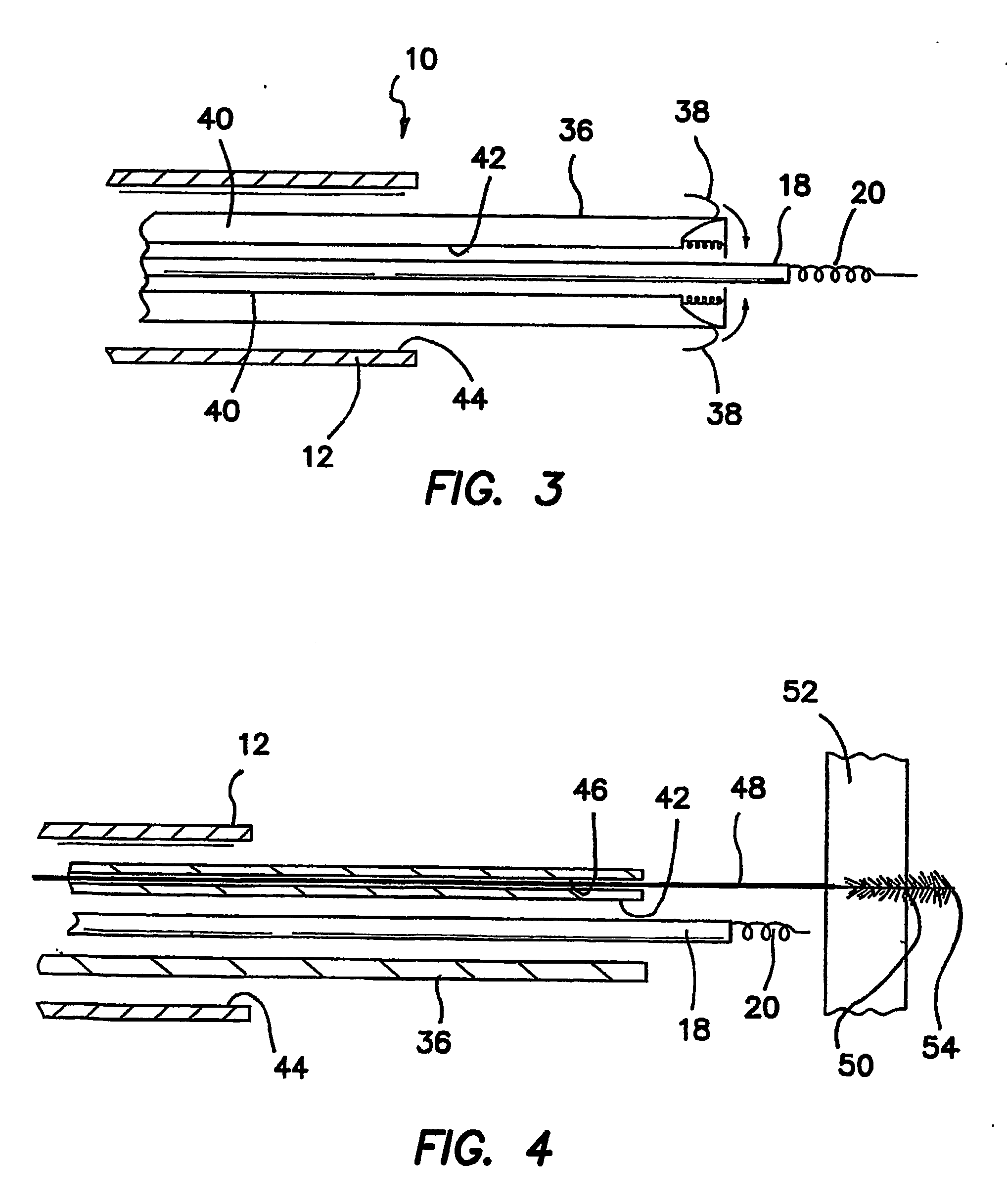
[0067]FIG. 3 is a side cross sectional view of the distal end of telescopic introducer 10 which is comprised of a prebiased introducer 36 through which pacemaker lead 18 with distal anchor 20 is implanted. The distal portion or end of introducer 36 is provided with one or more barbless hooks or “fish hooks”, which are normally resiliently retained within recesses defined in the wall of introducer 36. Hooks 38 can be deployed by pulling tension wires 40 coupled to hooks 38 to rotate hooks 38 out of the recesses in introducer 36 to a position where they may penetrate radially adjacent myocardium or vascular tissue. Once hooks 38 are deployed by pulling on wires 40, pacemaker 18 is anchored from the end of anchored introducer 36. Once pacemaker lead 18 is anchored, the tension on wires 40 is released, allowing springs or other resilient means attached to hooks 38 to return them to their undeployed configuration with recesses within introducer 36.

[0068] Again it must be understood that ...


PUM


Abstract

A pacemaker lead (18) is implanted by using a two anchor system. One anchor (916) to first secure the position of an introducer (14) through which the pacemaker lead will be implanted, and a second anchor (20) used for implanting the distal tip of the pacemaker lead (18). Examples of the anchors include various types of mechanical anchors or mechanical anchor combinations such as a suction anchor, a barbed needle, or a needle and balloon combination. The anchors can be used in the pericardial space in the heart by disposing an elongate instrument into the venous system of the heart; puncturing the venous system at a predetermined position; disposing the elongate instrument into the pericardial space at a predetermined location in the pericardial space; and implanting a pacemaker lead at the predetermined position.

Description

RELATED APPLICATIONS [0001] The present application is related to U.S. Provisional Patent Applications Ser. No. 60 / 426,773, filed on Nov. 15, 2002; Ser. No. 60 / 476,487, filed on Jun. 6, 2003; 60 / 479,399, filed on Jun. 18, 2003; and Ser. No. 60 / 464,437, filed on Apr. 22, 2003, which are each incorporated herein by reference and to which priority is claimed pursuant to 35 USC 119.BACKGROUND OF THE INVENTION [0002] 1. Field of the Invention [0003] The invention relates to the field of cardiology and in particular to apparatus and methods for pacemaker implantations. [0004] 2. Description of the Prior Art [0005] In many cases pacemaker introducers are precurved for steerability and use in the coronary sinus. Being precurved, such introducers cannot be rotated for the purpose of setting a screw-in anchor into myocardium, since their distal ends wobble uncontrollably while being rotated. It is nevertheless advantageous to anchor an introducer when similarly implanting or anchoring the muc...

Claims


Application Information

Patent Timeline
IPC IPC(8): A61N1/05A61MA61N1/00
CPCA61N1/0573A61N2001/0585A61N1/0587
Inventor KURTH, PAUL A.WORLEY, SETH J.
Owner KURTH
Why Eureka
Try Eureka