Sidelobe controlled radio transmission region in metallic panel

a radio transmission region and metallic panel technology, applied in the field of radio frequency (rf) communication, can solve the problems of limiting or preventing the transmission of rf signals into and out of buildings, significant drawbacks of using metallic panels in windows and other applications, and limiting or preventing the transmission of rf signals. to achieve the effect of facilitating rf transmission and facilitating rf transmission

Inactive Publication Date: 2006-01-19
THE OHIO STATES UNIV
View PDF81 Cites 24 Cited by
  • Summary
  • Abstract
  • Description
  • Claims
  • Application Information

AI Technical Summary

Problems solved by technology

Despite the many benefits, there is a significant drawback of using metallic panels in windows and other applications.
As a result, the use of metallic panels in windows can limit or prevent the transmission of RF signals into and out of buildings, vehicles, and other similar structures.

Method used


Image

  • Sidelobe controlled radio transmission region in metallic panel
  • Sidelobe controlled radio transmission region in metallic panel
  • Sidelobe controlled radio transmission region in metallic panel

Examples


examples

[0060] Multiple embodiments of the present invention have been tested. In summary, the testing shows that the theory of frequency selective surfaces as well as Fourier windowing techniques may be used to improve the transmission characteristics of an aperture of the present invention. With regard to FIGS. 10 through 17, test results are provided for both orthogonal (vertical) and parallel (horizontal) polarizations in the 500 MHz to 18 GHz frequency band. The results are based on simulations using a periodic moment method (PMM) computer calculation code. All data in these figures is normalized with respect to free space. In an actual window, there may be extra loss due to the glass which is not shown in these test results. Typically, a clear section of glass (e.g., about 5.4 mm thick) may cause about 2 to 3 dB of loss as compared to free space.

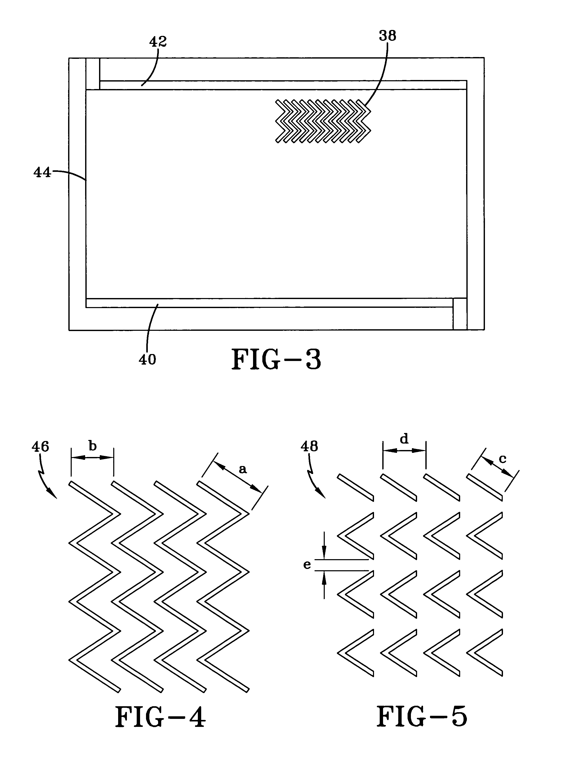
[0061]FIGS. 10 and 11 illustrate the transmission properties of one embodiment of an aperture of the present invention having broken, zigzag...


PUM


Abstract

A region in a metallic panel that facilitates the transmission of radio frequency signals. The metallic panel may be included in a window such as the window of a vehicle or building. For example, the metallic panel may be used for heating or to reflect infrared radiation. An aperture is formed in the metallic panel to enable radio frequency signals to be transmitted through the metallic panel. The design of the aperture may be selected to enable the transmission of the desired frequency band. Furthermore, the aperture is designed such that there is a taper in the transmission amplitude and / or the phase to suppress lobing effects on the other side of the aperture. In an embodiment in which the metallic panel is used to conduct electric current, the aperture may be oriented such that the current may flow between the openings of the aperture. Accordingly, there may be uniform heating across the metallic panel without blocking the transmission of radio frequency signals in the desired frequency band.

Description

BACKGROUND AND SUMMARY OF THE INVENTION [0001] This is a divisional of U.S. application Ser. No. 10 / 310,643, filed Dec. 4, 2002, which will issue as U.S. Pat. No. 6,860,081 on Mar. 1, 2005. Each priority document is incorporated by reference in its entirety. [0002] The present invention relates generally to radio frequency (RF) communication. More particularly, the present invention relates to a metallic panel that is adapted to enable radio frequency communication with sidelobe control. [0003] Metallic panels are used in a wide variety of applications. In fact, transparent, metallic panels are even used in windows of buildings and vehicles. Transparent, metallic panels may be used in building and vehicle windows in order to reflect infrared radiation, thereby limiting heat build up in the interior. Additionally, transparent, metallic panels may be used in vehicle windows in order to enable a flow of electric current across the window. In such embodiments, the flow of electricity is...

Claims


Application Information

Patent Timeline
Patent Type & Authority Applications(United States)
IPC IPC(8): E06B3/00E06B7/28H01Q1/12H01Q15/00
CPCE06B7/28Y10T428/12H01Q15/0053H01Q1/1271
Inventor WALTON, ERIC K.VOELTZEL, CHARLES S.
Owner THE OHIO STATES UNIV
Why Eureka
Try Eureka