
Method for optimizing the locating accuracy of an RFID tag in an ultra-high frequency radio range in a system for locating RFID tags comprising a plurality of reading devices

Inactive Publication Date: 2015-10-22
SKIDATA AG
View PDF6 Cites 3 Cited by
  • Summary
  • Abstract
  • Description
  • Claims
  • Application Information

AI Technical Summary

Benefits of technology

The present invention provides a method for improving the accuracy of locating RFID tags in a system with multiple reading devices. By simulating and measuring the location and volume of cold spots, or points with minimal amplitude, the method allows for accurate tag location without changing the system components. This increases locating accuracy without adding high costs and can be used with either active or passive RFID tags.

Problems solved by technology

The reflections can overlap, which can lead to amplification or in extreme cases to extinction, and often arrive multiple times at the receiver due to multipath propagation, thus significantly degrading the locating accuracy.
Systems comprising a plurality of reading devices can result in superimposition of the UHF signals transmitted by the individual reading devices, thus negatively affecting the detection and locating accuracy.
However, only a static problem in dependence on the environment is solved by this procedure.
Disadvantageously, dynamic changes that occur, for example, when a person enters a room are not detected with this method.
However, numerous reference tags distributed in the room and many reference measurements are required for sufficient accuracy, which disadvantageously results in a reduced effective reading rate of the objects or persons to be identified.
This creates hotspots, i.e., spots with maximum amplitude, and cold spots, i.e., spots with minimum amplitude, in the room due to the changing constructive and destructive superimposition of the UHF waves of the individual reading devices.
If an RFID tag is located in a cold spot, not enough energy is available in the UHF field that would enable the RFID tag to respond to the request of one or more reading devices.

Method used


Image

  • Method for optimizing the locating accuracy of an RFID tag in an ultra-high frequency radio range in a system for locating RFID tags comprising a plurality of reading devices
  • Method for optimizing the locating accuracy of an RFID tag in an ultra-high frequency radio range in a system for locating RFID tags comprising a plurality of reading devices
  • Method for optimizing the locating accuracy of an RFID tag in an ultra-high frequency radio range in a system for locating RFID tags comprising a plurality of reading devices

Examples


Embodiment Construction

[0022]The preferred embodiments of the present invention will now be described with reference to FIGS. 1-3 of the drawings.

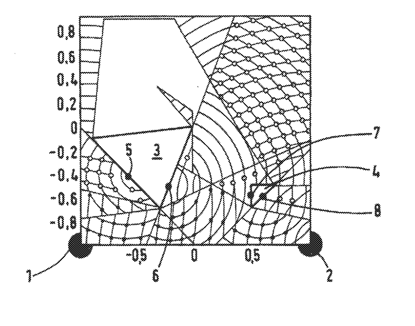
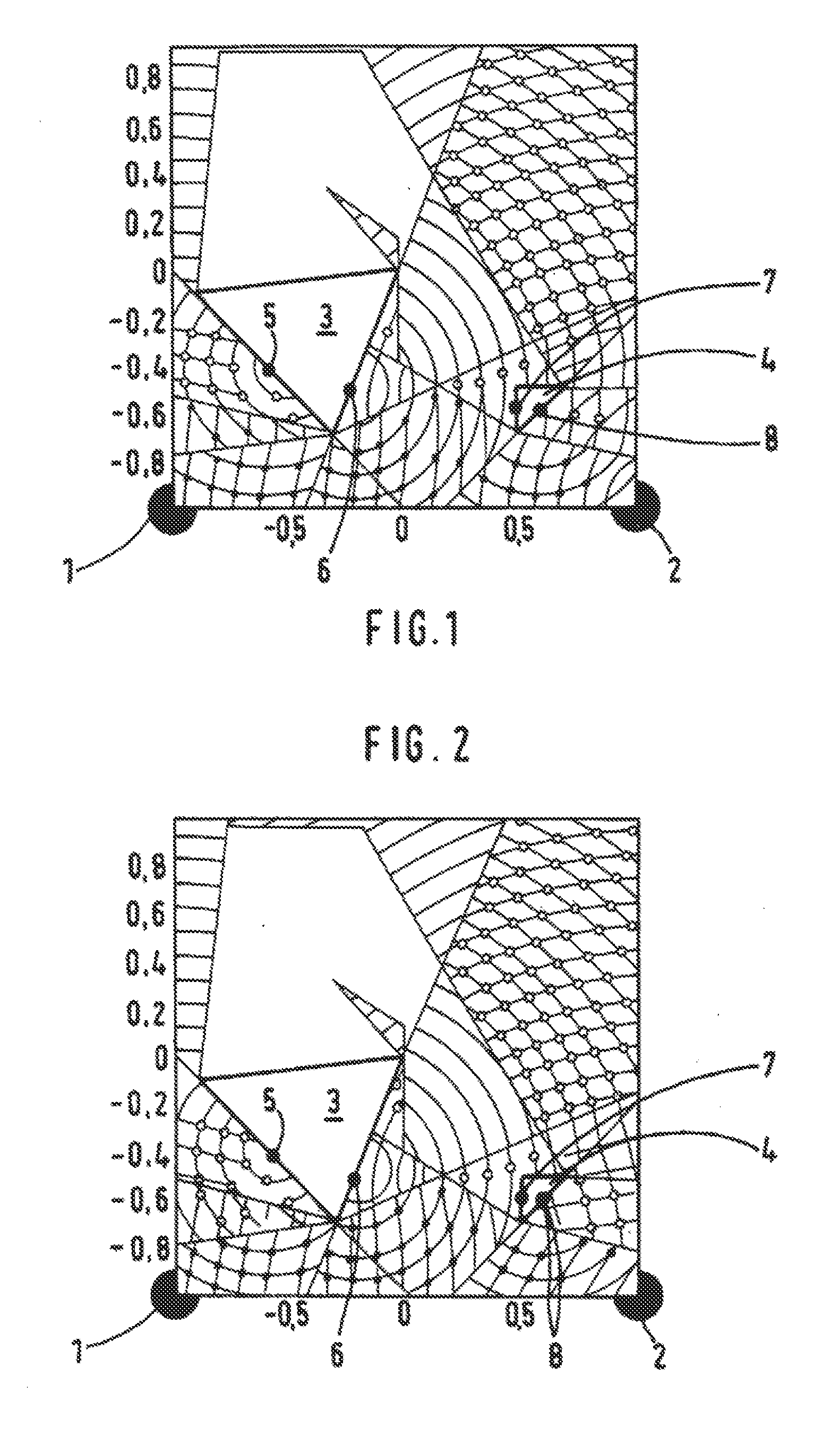
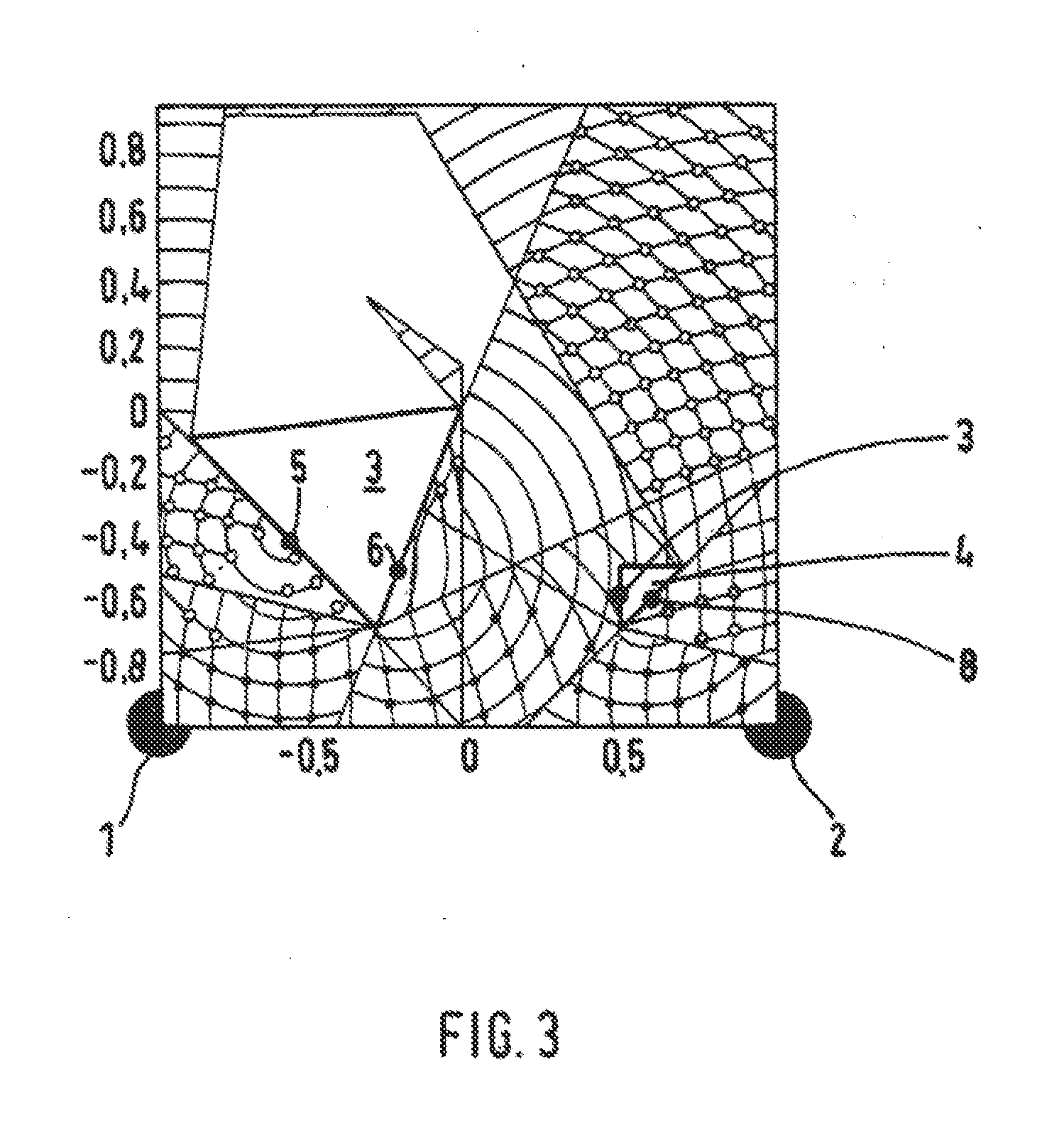
[0023]The accompanying FIGS. 1, 2 and 3 show a room with the corner points defined by their coordinates {(1,1) (1,−1) (−1,−1) (−1,1)}. Installed in the room are two reading devices in stationary locations, which are shown as black dots in the corner points 1 and 2 [at coordinates (−1, −1) and (1, −1) respectively]. Also located in the room are two objects 3 and 4, which are configured as triangles in exemplary fashion in the two-dimensional presentation of the figures. A lighter presentation of the field here indicates higher field strength.

[0024]The UHF field of the reading devices 1, 2 is shielded by the objects 3, 4, such that a UHF field can no longer be detected in the areas behind the objects. Also, the UHW waves sent from the reading devices 1, 2 are reflected by the objects 3, 4 at the impact surfaces, which are modeled by virtual radiation sources 5, 6,...


PUM


Abstract

In a method for optimizing the locating accuracy of an RFID tag in an ultra-high frequency radio range in a system for locating RFID tags in a room comprising a plurality of reading devices, a first step of locating of the RFID tag is initially carried out using methods known from the prior art, whereby for this purpose the RFID tag is detected by at least one reading device. Thereafter cold spots, i.e., points with minimal amplitude, are generated or moved in a targeted fashion in the room using a predetermined variation of the phase position, the frequency and / or the transmission amplitude of the individual reading devices, whereby their location and volume as a function of the phase position, the frequency and the transmission amplitude of the individual reading devices is known by means of simulations and / or measurements. If an RFID tag is no longer detected by any reading device, the same is located in a cold spot, which is identified by means of the first, rough locating of the RFID tag using methods known from the prior art, which allows for accurate locating of the RFID tag.

Description

BACKGROUND OF THE INVENTION[0001]The present invention relates to a method for optimizing the locating accuracy of an RFID tag in an ultra-high frequency radio range in a system for locating RFID tags comprising a plurality of reading devices.[0002]The RFID technology, in particular in the ultra-high frequency range (UHF) is known to a persons skilled in the art and has been used for some time in various applications. This includes applications in the fields of logistics, people and vehicle identification and also applications in the field of indoor navigation. Here, locating systems for RFID tags (RFID transponders) in an ultra-high frequency radio range comprise one or more UHF reading devices as well as a plurality of active and / or passive UHF RFID tags. Depending on the design of the system, either the reading devices or the UHF RFID tags are mobile, while the respective counterpart, i.e., the UHF RFID tags or the reading devices, are designed to be stationary.[0003]Basically, e...

Claims


Application Information

Patent Timeline
IPC IPC(8): H04W4/02G06K7/10
CPCG06K7/10366H04W4/02G01S7/40G01S13/726G01S13/74G01S13/876G06K7/10198
Inventor SCHLECHTER, THOMAS
Owner SKIDATA AG
Learn More