
Switching structures for hearing aid

a technology of switching structure and hearing aid, which is applied in the field of hearing aids, can solve the problems of difficult manual or mechanical operation of a switch to change the input or operation characteristics of a hearing aid, difficulty in manually engaging a switch in a hearing aid that is mounted within the ear canal, and may be impossible, and achieves the effect of high sensitivity amr material

Active Publication Date: 2006-01-19
STARKEY LAB INC
View PDF98 Cites 84 Cited by
  • Summary
  • Abstract
  • Description
  • Claims
  • Application Information

AI Technical Summary

Benefits of technology

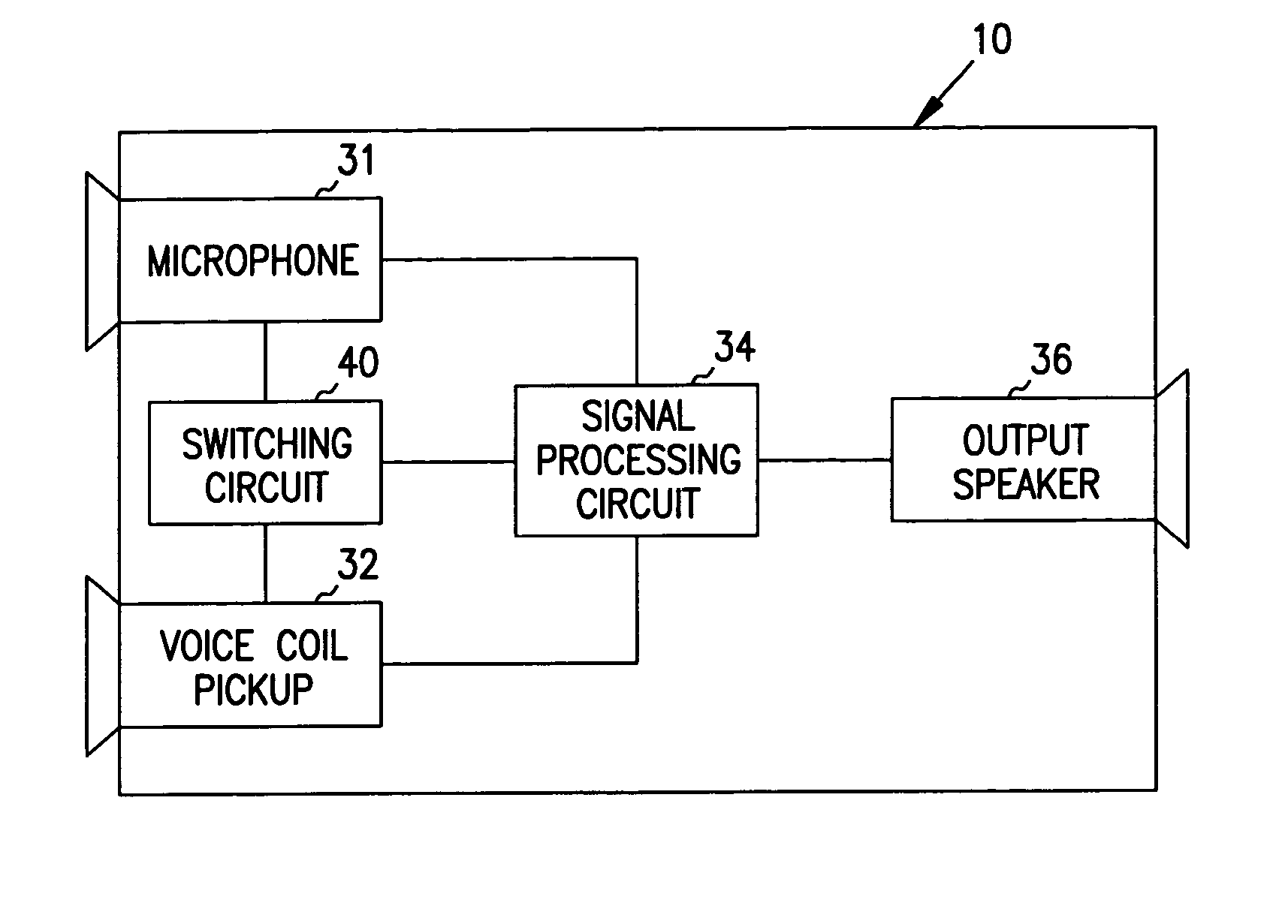
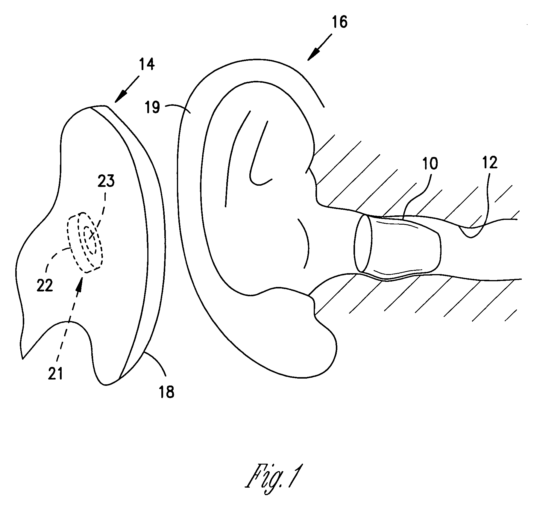
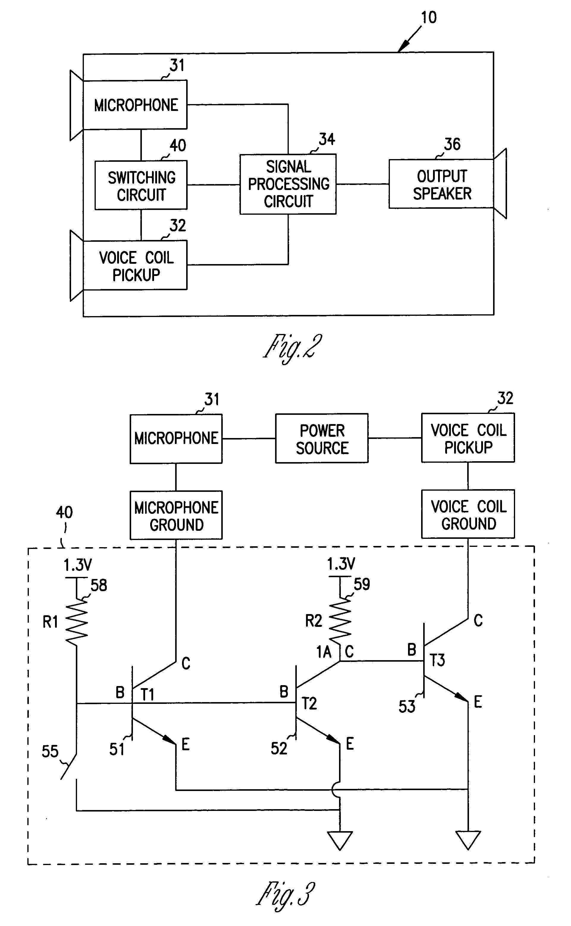
The present invention relates to an apparatus and methods for detecting information modulated on a time varying magnetic field using a GMR or AMR sensor in a hearing assistance device. The sensor is connected to an input system and a signal processing circuit, which produces an acoustic signal for output by a speaker. The sensor can detect a magnetic field in proximity to the device, and the system can select between an acoustic input and the information modulated on the magnetic field based on the detection of the magnetic field. The sensor can be a spin dependent tunneling sensor or a high sensitivity AMR material. The technical effects of the invention include improved magnetic sensing and detection of information modulated on a time varying magnetic field, which can enhance the accuracy and efficiency of hearing assistance devices.

Problems solved by technology

It can be a drawback to require manual or mechanical operation of a switch to change the input or operational characteristics of a hearing aid.
Moreover, manually engaging a switch in a hearing aid that is mounted within the ear canal is difficult, and may be impossible, for people with impaired finger dexterity.
Such an action takes time and adequate time may not be available to cycle through the settings to arrive at the required setting, for example, there may be insufficient time to arrive at the required volume when answering a telephone.
However, quickly manually switching the input of the hearing aid from a microphone to a voice coil, by a manual mechanical switch or by a magnetic actuator, may be difficult for some hearing aid wearers.

Method used


Image

  • Switching structures for hearing aid
  • Switching structures for hearing aid
  • Switching structures for hearing aid

Examples


Embodiment Construction

[0046] In the following detailed description, reference is made to the accompanying drawings which form a part hereof and in which are shown by way of illustration specific embodiments in which the invention can be practiced. These embodiments are described in sufficient detail to enable those skilled in the art to practice and use the invention, and it is to be understood that other embodiments may be utilized and that electrical, logical, and structural changes may be made without departing from the spirit and scope of the present invention. The following detailed description is, therefore, not to be taken in a limiting sense and the scope of the present invention is defined by the appended claims and their equivalents.

[0047] Hearing aids provide different hearing assistance functions including, but not limited to, directional and non-directional inputs, multi-source inputs, filtering and multiple output settings. Hearing aids are also provide user specific and / or left or right e...


PUM


Abstract

An apparatus is provided that includes an input system, an output system, and a sensor for sensing magnetic fields. In one example, a signal processing circuit electrically connects the input system to the output system, and a magnetic sensor adapted to inhibit the acoustic input and function as a magnetic input in the presence of a magnetic field. In one example, the magnetic sensor includes a giant magneto resistive (GMR) sensor. In another example, the magnetic sensor includes an anisotropic magneto resistive (AMR) sensor. The magnetic field can be generated by, among other things, a magnet in a telephone handset. The hearing aid further is programmed based on time-varying characteristics of the magnetic field. Wireless activation or deactivation of the hearing aid is also described. Other examples and options are provided herein.

Description

RELATED APPLICATIONS [0001] The present application is a continuation-in-part (CIP) of U.S. application Ser. No. 10 / 244,295, filed Sep. 16, 2002, and titled SWITCHING STRUCTURES FOR HEARING AID, which is hereby incorporated by reference. [0002] The present application is generally related to U.S. application Ser. No. 09 / 659,214, filed Sep. 11, 2000, and titled AUTOMATIC SWITCH FOR HEARING AID, which is hereby incorporated by reference. [0003] The present application is generally related to U.S. application Ser. No. 10 / 243,412, filed Sep. 12, 2002, and titled DUAL EAR TELECOIL SYSTEM, which is hereby incorporated by reference.FIELD OF THE INVENTION [0004] This invention relates generally to hearing aids, and more particularly to switching structures and systems for a hearing aid. BACKGROUND [0005] Hearing aids can provide adjustable operational modes or characteristics that improve the performance of the hearing aid for a specific person or in a specific environment. Some of the oper...

Claims


Application Information

Patent Timeline
Patent Type & Authority Applications(United States)
IPC IPC(8): H04R25/00
CPCH04R25/43H04R25/554H04R25/558H04R2225/31H04R2460/17H04R2460/03H04R25/50H04R25/305H04R2225/51
Inventor SACHA, MICHAEL KARL
Owner STARKEY LAB INC
Learn More