Spinal stabilization devices coupled by torsional member

a technology of spinal stabilization and torsional member, which is applied in the direction of prosthesis, instruments, gearing, etc., can solve the problems of accelerating degeneration at those levels, reducing range of motion, and affecting the stability of spinal nerves, and achieve the effect of contributing to spinal stability

Inactive Publication Date: 2006-01-19
APPLIED SPINE TECH
View PDF62 Cites 126 Cited by
  • Summary
  • Abstract
  • Description
  • Claims
  • Application Information

AI Technical Summary

Benefits of technology

[0012] The present disclosure provides advantageous apparatus and methods for stabilizing adjacent spinal vertebrae in spinal axial rotation and spinal lateral bending. According to an exemplary embodiment, first and second stabilization members of a spine stabilization system are configured for coupling with respect to first and second pedicle screw pairs. The pedicle screw pairs are typically implanted in adjacent vertebrae, and the stabilization devices that extend therebetween contribute spinal stability. According to exemplary embodiments of the present disclosure, the stabilization devices are dynamic stabilization devices that include elastic elements (e.g., springs) that deliver desirable force profiles in situ.
[0014] The torsion member is typically mounted with respect to a mounting / attachment member associated with each of the pedicle screw pairs. Stabilization is achieved through the torsion member's interaction with the respective first and second attachment members. In this way, the torsion member is able to further stabilize the adjacent spinal vertebrae with respect to spinal axial rotation and / or spinal lateral bending. The torsion member is configured and dimensioned to accommodate interaction with the respective first and second attachment members and includes a geometry that is characterized as follows: (i) a first segment that is substantially co-planar with and perpendicular to the axis of the first stabilization member; (ii) a second segment that extends from the first segment and that is angularly and upwardly oriented relative to the first segment; (iii) a third segment that extends from the second segment, substantially perpendicular to the first stabilization device and oriented in a plane that is elevated with respect to but parallel to the plane of the first stabilization device, (iv) a fourth segment that extends from the third segment and that is a substantial mirror image of the second segment; and (v) a fifth segment that extends from the fourth segment and that is a substantial mirror image of the first segment. Thus, exemplary embodiments of the disclosed torsion member are substantially symmetrical relative to a mid-point of the third segment.

Problems solved by technology

Low back pain is one of the most expensive diseases afflicting industrialized societies.
While fusion is effective about seventy percent of the time, there are consequences even to these successful procedures, including a reduced range of motion and an increased load transfer to adjacent levels of the spine, which accelerates degeneration at those levels.
Further, a significant number of back-pain patients, estimated to exceed seven million in the U.S., simply endure chronic low-back pain, rather than risk procedures that may not be appropriate or effective in alleviating their symptoms.
Clinical studies have also found that the range of motion increase does not correlate well with low back pain.

Method used


Image

  • Spinal stabilization devices coupled by torsional member
  • Spinal stabilization devices coupled by torsional member
  • Spinal stabilization devices coupled by torsional member

Examples


Embodiment Construction

[0038] Exemplary embodiments of the disclosed dynamic stabilization system / device are presented herein. It should be understood, however, that the disclosed embodiments are merely exemplary of the present invention, which may be embodied in various forms. Therefore, the details disclosed herein are not to be interpreted as limiting, but merely as the basis for teaching one skilled in the art how to make and / or use the devices and systems of the present disclosure.

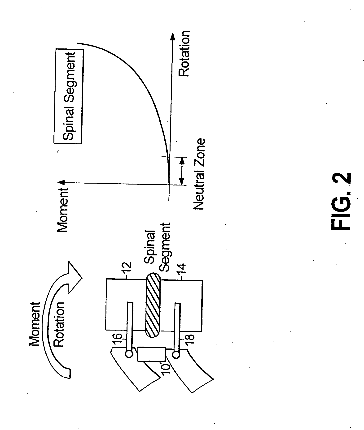
[0039] With reference to FIGS. 2, 3a-e and 4, a method and apparatus are disclosed for spinal stabilization. In accordance with a preferred embodiment of the present disclosure, the spinal stabilization method is achieved by securing an internal dynamic spine stabilization device 10 between adjacent vertebrae 12, 14 and providing mechanical assistance in the form of elastic resistance to the region of the spine to which the dynamic spine stabilization device 10 is attached. The elastic resistance is applied as a function o...


PUM


Abstract

Spine stabilization devices, systems and methods are provided in which torsion member extends between first and second stabilization devices that are oppositely positioned relative to the vertebrae. The torsion member includes a (i) a first segment that is substantially co-planar with and perpendicular to the axis of at least one of the stabilization devices; (ii) a second segment that extends from the first segment and that is angularly and upwardly oriented relative to the first segment; (iii) a third segment that extends from the second segment, is substantially perpendicular to at least one of the stabilization devices, and is oriented in a plane that is elevated with respect to, but substantially parallel to, the plane of at least one of the stabilization devices, (iv) a fourth segment that extends from the third segment and that is a substantial mirror image of the second segment; and (v) a fifth segment that extends from the fourth segment and that is a substantial mirror image of the first segment.. Methods for mounting the torsion member with respect to attachment members associated with opposed pedicle screws are also disclosed.

Description

CROSS-REFERENCE TO RELATED APPLICATIONS [0001] The present application claims the benefit of a co-pending provisional patent application entitled “Dynamic Spine Stabilizer,” filed on Jun. 23, 2004 and assigned Ser. No. 60 / 581,716. The entire contents of the foregoing provisional patent application are incorporated by reference herein.BACKGROUND OF THE DISCLOSURE [0002] 1. Technical Field [0003] The present disclosure is directed to a dynamic stabilization device and system for spinal implantation and, more particularly, to a dynamic stabilization device and system that is adapted to be positioned / mounted relative to first and second laterally-spaced pedicle screws and that includes at least one dynamic stabilization member that is positioned beyond the region defined between the pedicle screws, e.g., in an “overhanging” orientation. [0004] 2. Background Art [0005] Low back pain is one of the most expensive diseases afflicting industrialized societies. With the exception of the commo...

Claims


Application Information

Patent Timeline
Patent Type & Authority Applications(United States)
IPC IPC(8): A61F2/30A61B17/70A61B17/86
CPCA61B17/7007A61B17/702A61B17/7026Y10T74/22A61B17/7041A61B17/7049A61B17/7028
Inventor PANJABI, MANOHAR M.TIMM, JENS PETER
Owner APPLIED SPINE TECH
Why Eureka
Try Eureka