Exhaust gas purifying apparatus

Active Publication Date: 2006-01-26
DENSO CORP
View PDF12 Cites 26 Cited by
  • Summary
  • Abstract
  • Description
  • Claims
  • Application Information

AI Technical Summary

Benefits of technology

[0008] The present invention is made in view of the above problems. It is an object of the present invention to provide an exhaust gas purifying apparatus, in which a temperature of an inside of the DPF can be accu

Problems solved by technology

In such an exhaust gas purifying apparatus, an over-heat of the DPF has become a problem.
The over-heat of the DPF may result from a rapid combustion of the accumulated diesel particulates in the DPF, and may cause a problem in that a breakage of the DPF or a deterioration of catalyst supported by the DPF may occur due to a rapid increase of the temperature of the DPF.
It is, however, not possible to directly detect temperatures at an inside of the DPF by a temperature sensor.
However, heat generation is taking place in the inside of the DPF due to the combustion of the diesel particulat

Method used


Image

  • Exhaust gas purifying apparatus
  • Exhaust gas purifying apparatus
  • Exhaust gas purifying apparatus

Examples


Example

[0036] An exhaust gas purifying apparatus for a diesel engine, to which the present invention is applied, is explained with reference to the drawings.

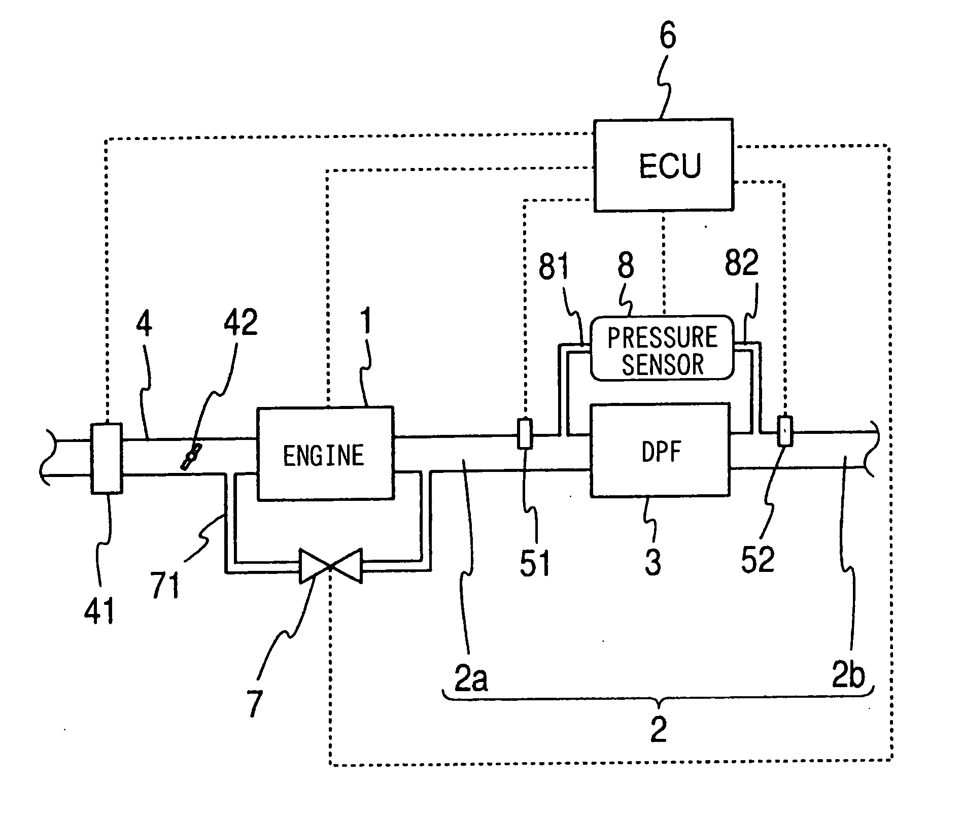
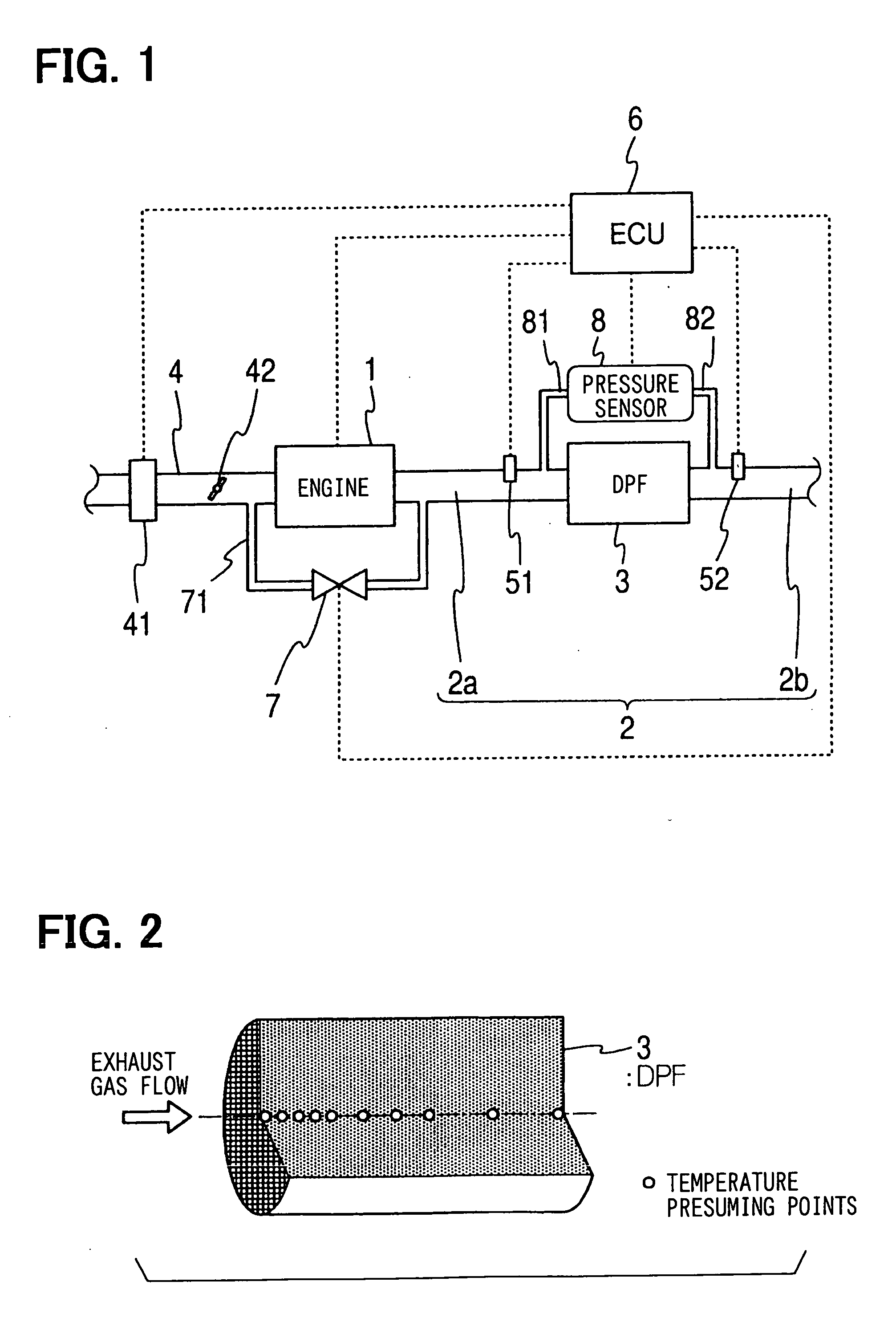
[0037]FIG. 1 is a schematic view showing an exhaust gas purifying system according to an embodiment of the present invention. A diesel particulate filter (hereinafter also referred to as DPF) is provided between exhaust gas pipes 2a and 2b, forming an exhaust gas passage 2 of a diesel engine 1. The DPF 3 is a ceramic filter having a well-known structure, for example a honeycomb structure formed from a heat-resisting ceramic, such as cordierite or the like, and having multiple cells for forming gas passages, wherein inlet sides and outlet sides of the cells are alternately closed. The exhaust gas from the engine 1 flows toward a downstream side, passing through porous portioning walls of the DPF 3. The diesel particulates (PM) are trapped by and gradually accumulated in the DPF 3.

[0038] An oxidation catalyst is generally supported by ...


PUM


Abstract

In an exhaust gas purifying apparatus for a diesel engine having a diesel particulate filter (DPF) provided in an exhaust pipe, a temperature of the DPF is indirectly detected (presumed) to prevent an over-heat of the DPF during a re-generation operation thereof. For that purpose, the DPF is hypothetically divided into multiple cells, the temperature at the respective cells is presumed based on a heat budget of the cell, and the maximum temperature among those multiple presumed temperatures is controlled to be lower than a predetermined value.

Description

CROSS REFERENCE TO RELATED APPLICATION [0001] This application is based on Japanese Patent Application No. 2004-214641, which is filed on Jul. 22, 2004, the disclosure of which is incorporated herein by reference. FIELD OF THE INVENTION [0002] The present invention relates to an exhaust gas purifying apparatus for an internal combustion engine having a diesel particulate filter (DPF) in an exhaust pipe, and more particularly relates to the exhaust gas purifying apparatus and a method in which an over-heat of the DPF during a re-generation operation thereof is prevented. BACKGROUND OF THE INVENTION [0003] An exhaust gas purifying apparatus has become important, in which exhaust gas from an engine is processed by a catalyst or a filter so that emission of harmful components is suppressed in view of environmental protection. An exhaust gas purifying apparatus is known in the art, for example, in which a diesel particulate filter (DPF) is provided in an exhaust pipe of an engine for tra...

Claims


Application Information

Patent Timeline
IPC IPC(8): F02M25/06F01N3/00
CPCF01N9/002Y02T10/47F01N9/005Y02T10/40
Inventor OKUGAWA, SHINICHIROKOBAYASHI, KAZUO
Owner DENSO CORP
Why Eureka
Try Eureka