Torque reaction damper for a drive axle

a technology of torque reaction and damper, which is applied in the direction of rigid suspensions, resilient suspensions, vehicle components, etc., can solve the problems of destabilizing the car and causing the car to tend to turn l

Inactive Publication Date: 2006-01-26
HUPPERICH HERBERT L JR
View PDF21 Cites 28 Cited by
  • Summary
  • Abstract
  • Description
  • Claims
  • Application Information

AI Technical Summary

Benefits of technology

[0033] This suspension system allows a relatively large amount of vertical movement of the axle, with the trailing arms on each side of the axle allowing each end of the axle to move upwardly and downwardly a different amount from the other. The geometry of the trailing arm suspension system results in the end of the axle, which travels further downward, also moving somewhat forward in the chassis. This results in the axle positioning itself at an angle across the chassis, which results in the two drive wheels driving at an angle, rather than being parallel to the longitudinal axis of the chassis. The lower wheel is toed-in to some extent, i.e., driving inwardly toward the chassis, while the higher wheel is toed outwardly, driving away from the chassis.

Problems solved by technology

This results in the axle positioning itself at an angle across the chassis, which results in the two drive wheels driving at an angle, rather than being parallel to the longitudinal axis of the chassis.
The angular positioning of the axle also results in a misalignment of the drive wheels to the right, causing the car to tend to turn left.
In fact, the condition is sufficiently extreme that oversteer results, with the driver having to countersteer to the outside of the turn.
The problem occurs when the driver closes the throttle to slow for turn entry to the next turn.
This sudden reduction of torque causes the chassis to slam downwardly on the previously high left side, which destabilizes the car at a point where stability is critical.

Method used


Image

  • Torque reaction damper for a drive axle
  • Torque reaction damper for a drive axle
  • Torque reaction damper for a drive axle

Examples


Embodiment Construction

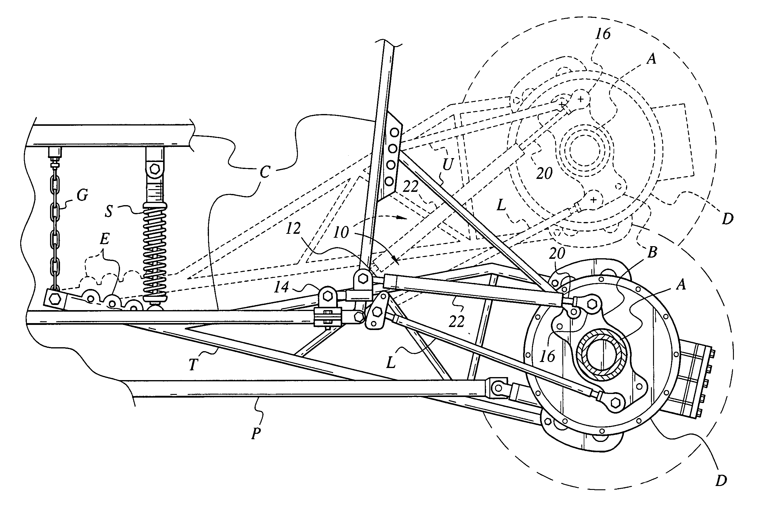
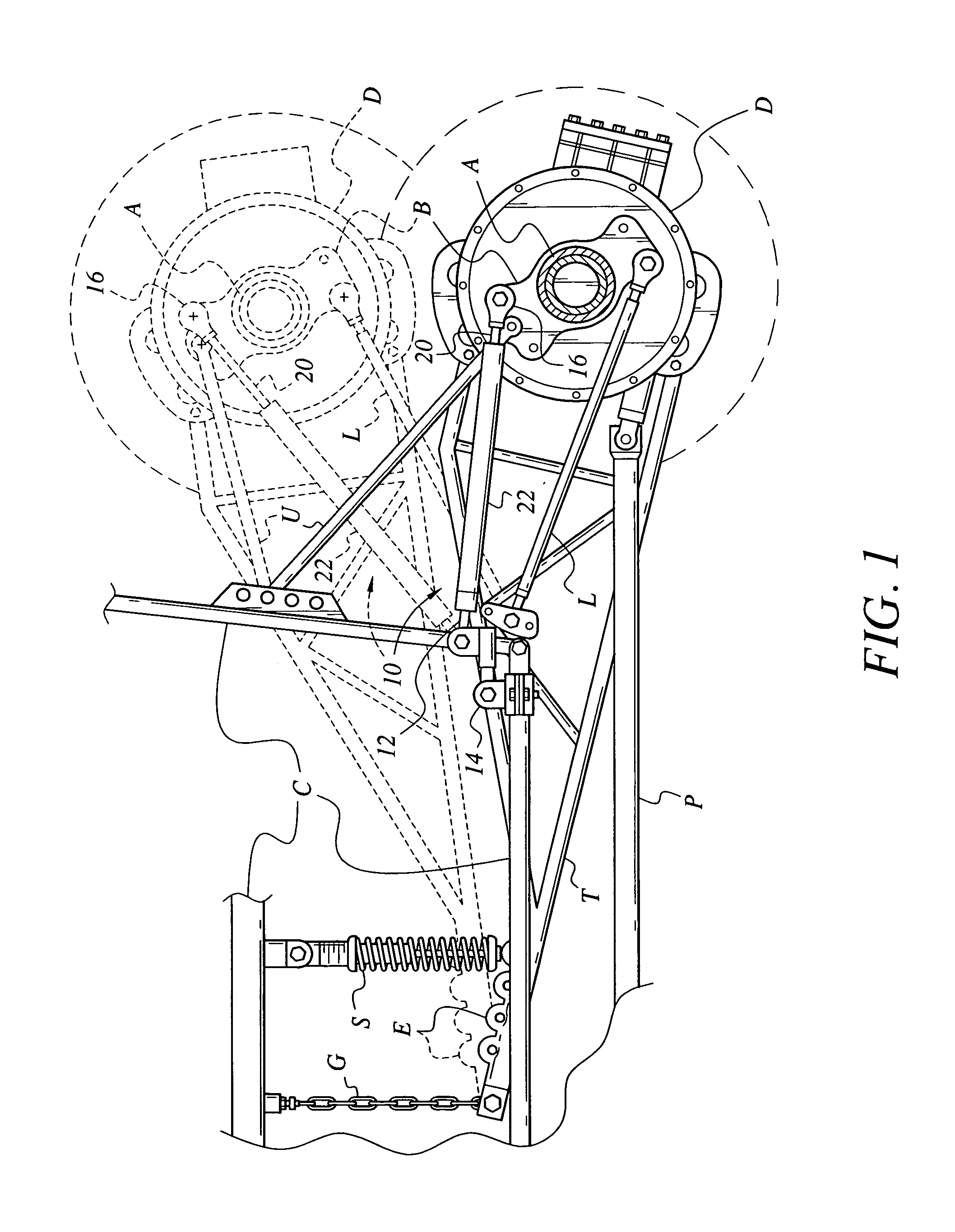
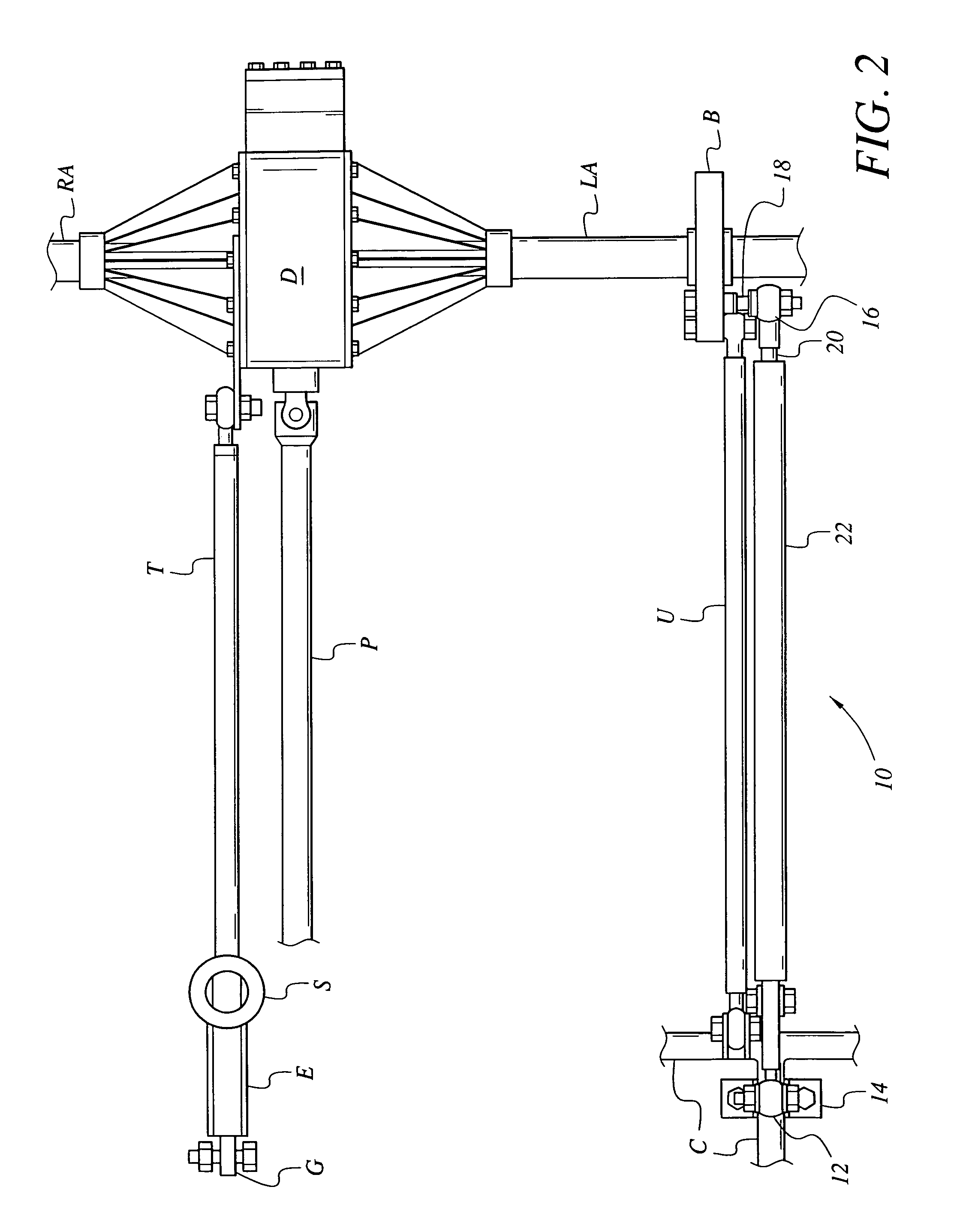
[0046] The present invention comprises a series of embodiments of a torque reaction damper for softening or dampening the sudden “chassis drop” which occurs when the throttle is suddenly closed in driving a dirt track late model (DTLM) racing car. Such vehicles are required by their governing rules to have solid rear drive axles, i.e., axles comprising non-rotating left and right housings or sleeves extending from a generally centrally positioned differential, with the rear drive axle shafts rotating within the housings or sleeves. Such vehicles are generally set up to have intentionally “loose” rear suspensions for their solid drive axles in order to achieve certain benefits in traction when power is applied, as described further above. However, when power is suddenly reduced, as when approaching a turn, the result is sudden, destabilizing “chassis drop” with such suspension systems. Obviously, drivers can accommodate the chassis drop problem, but the sudden change in vehicle confi...


PUM


Abstract

The present torque reaction damper for a drive axle is a series of embodiments of installations and attachment bracketry for use in dirt track late model (DTLM) racing vehicles. Such cars are set up to provide relatively large vertical deflections of the solid rear drive axle, to drive the inboard wheel downwardly against the track surface for better traction and to shift the axle angularly to promote oversteer through the turns when the throttle is applied. The present torque reaction damper solves the problem of sudden “chassis drop” and its destabilizing effect, when the throttle is suddenly closed at the end of a straight before entering a turn. The present damper comprises a shock absorber installed either forwardly or rearwardly between the “bird cage” axle bracket and the chassis and serves to cushion the movement of the chassis when the throttle is closed, thereby facilitating car stability and control.

Description

BACKGROUND OF THE INVENTION [0001] 1. Field of the Invention [0002] The present invention relates generally to automotive suspension systems, and more particularly to a shock absorber or damper installed between the chassis or frame and an attachment point on the axle of an automobile having a solid rear drive axle. The present damper is particularly suited for installation on a dirt track modified race car having extensive rear axle and rear suspension travel in order to dampen the sudden movement of the chassis relative to the axle during the transition from acceleration to deceleration. [0003] 2. Description of the Related Art [0004] Innumerable suspension systems and geometries have been developed for automotive vehicles over the years. The most common type of rear suspension system used with front engine, rear drive vehicles has been the solid rear axle, in which the differential and left and right axle tubes or housings are cast or otherwise formed as a single unit with no rel...

Claims


Application Information

Patent Timeline
Patent Type & Authority Applications(United States)
IPC IPC(8): B60G1/00
CPCB60G9/00B60G2200/314B60G13/001
Inventor HUPPERICH, HERBERT L. JR.
Owner HUPPERICH HERBERT L JR
Why Eureka
Try Eureka