Eureka AIR delivers breakthrough ideas for toughest innovation challenges, trusted by R&D personnel around the world.

Methods and systems for automatic zero calibration of radar altimeters

Inactive Publication Date: 2006-01-26
HONEYWELL INT INC
View PDF14 Cites 8 Cited by
  • Summary
  • Abstract
  • Description
  • Claims
  • Application Information

AI Technical Summary

Problems solved by technology

In addition, normal day to day aircraft operations and maintenance may result in variations and inaccuracies in altitude readings provided by a radar altimeter.
These variations and inaccuracies may be particularly noticeable when the aircraft is on the ground.

Method used


Image

  • Methods and systems for automatic zero calibration of radar altimeters
  • Methods and systems for automatic zero calibration of radar altimeters
  • Methods and systems for automatic zero calibration of radar altimeters

Examples


Embodiment Construction

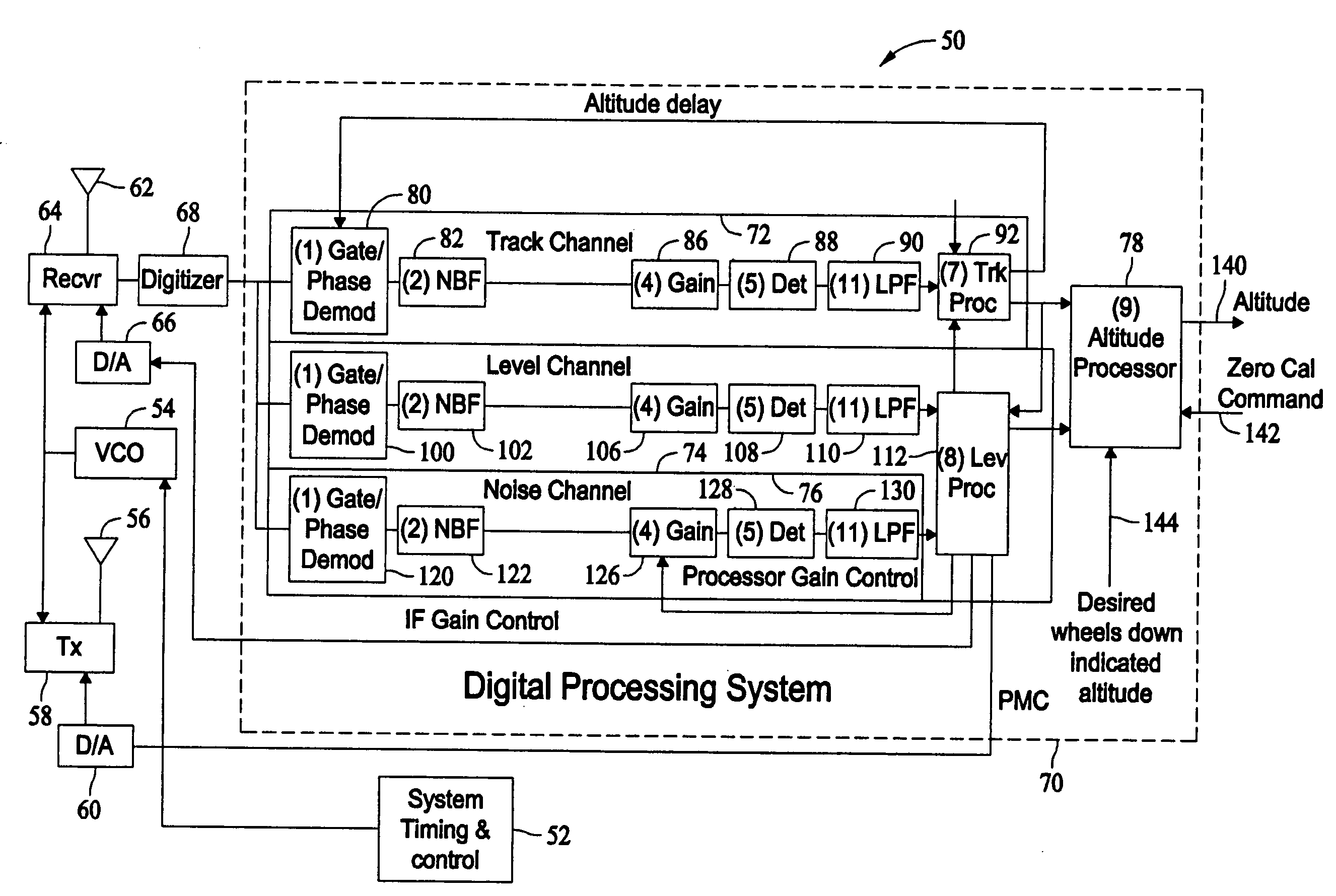
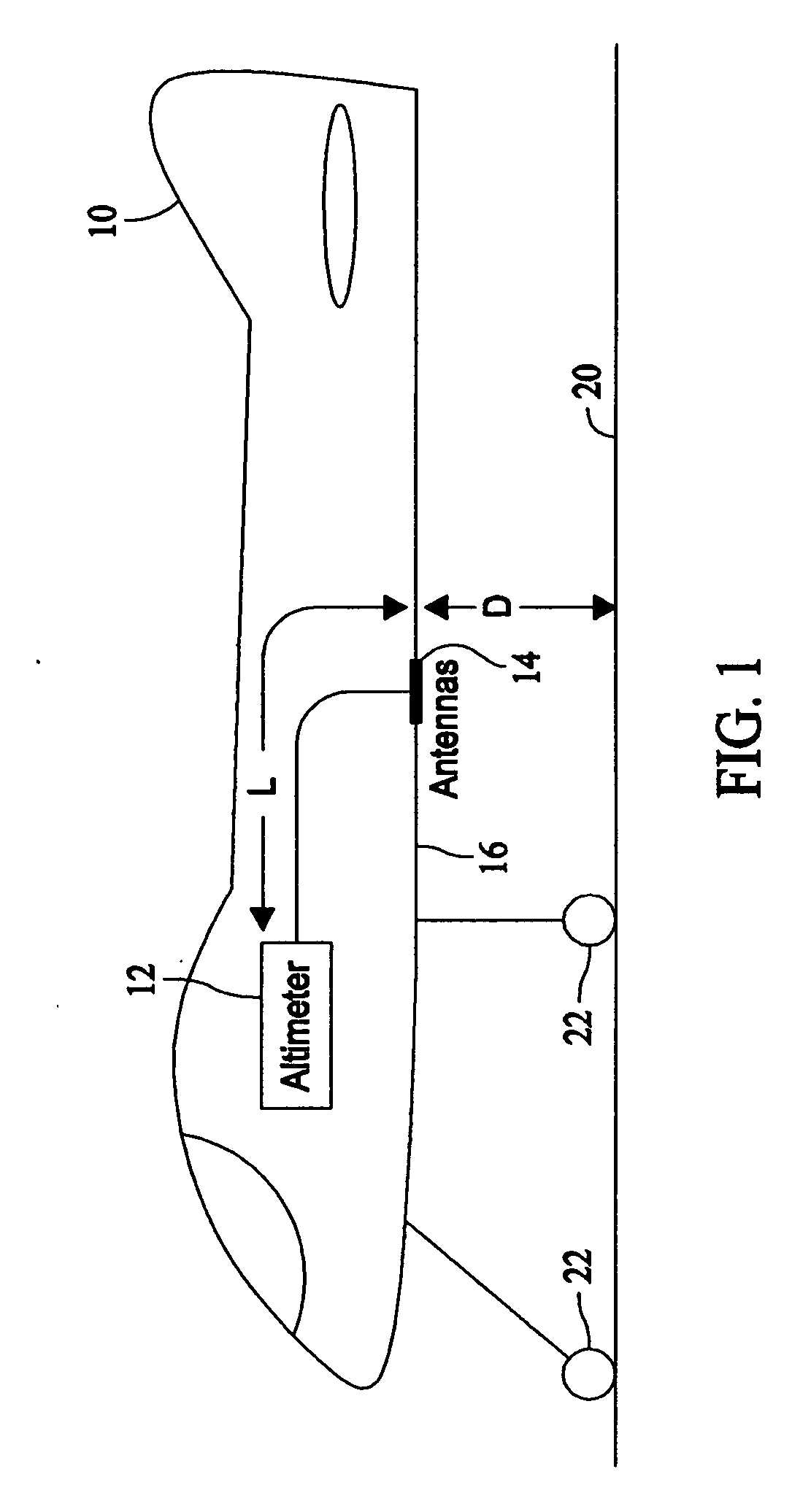
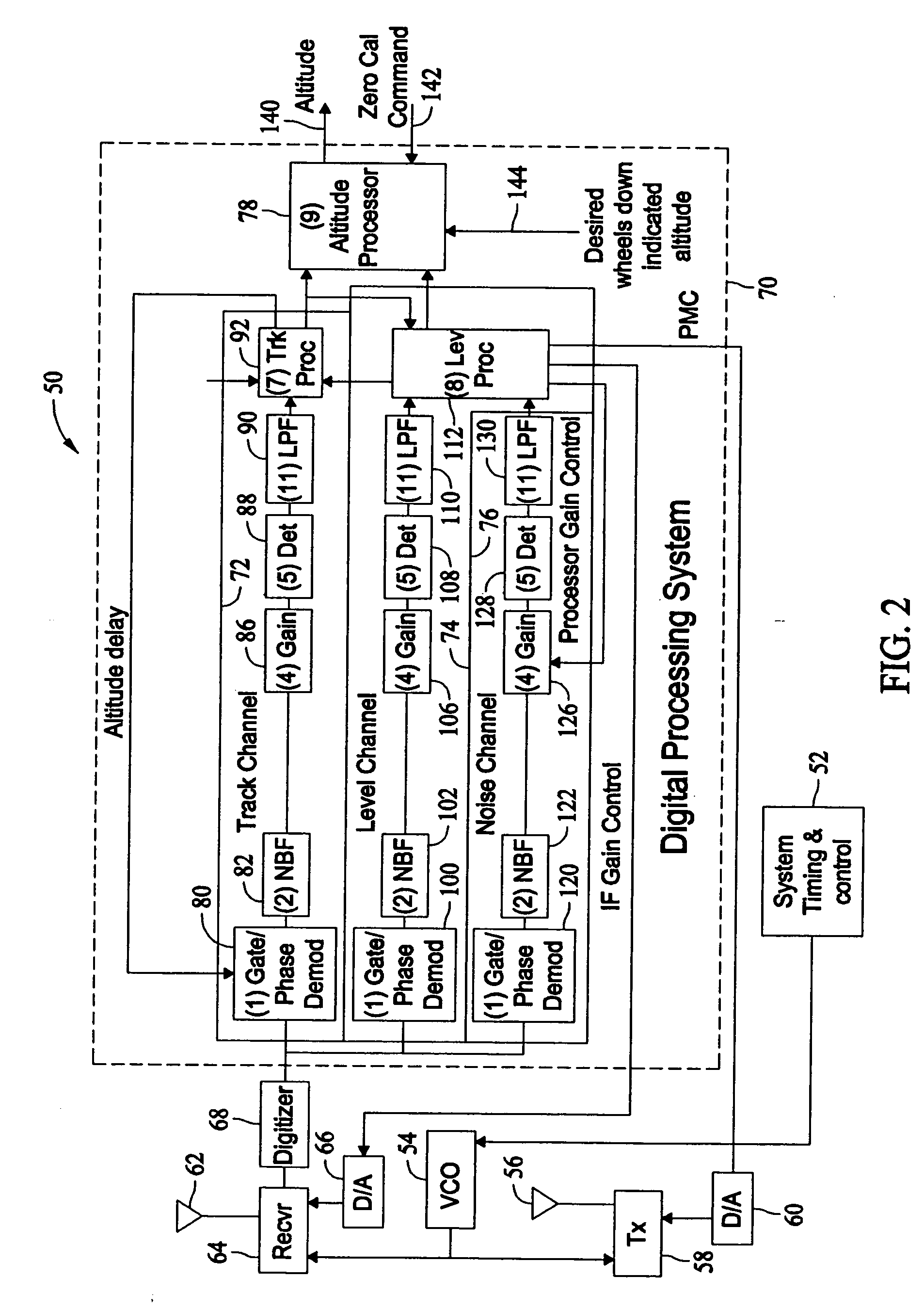
[0011]FIG. 1 is a diagram illustrating a typical radar altimeter installation within an air vehicle 10. Installed within aircraft 10 is a radar altimeter 12 which includes one or more antennas 14 that are mounted on a surface 16 of aircraft 10. Antennas 14 are a distance “L” from radar altimeter 12, and radar altimeters (e.g. radar altimeter 12) are typically calibrated to account for the delay in signal transmissions and receptions caused by the separation of radar altimeter 12 and antennas 14. Aircraft 10 is either parked on or taxiing along ground 20 as landing gears 22 are touching ground 20. As illustrated by FIG. 1, although aircraft 10 has a zero altitude (e.g., aircraft is on ground 20), antennas 14 of radar altimeter 12 are a distance “D” from ground 20. Absent any type of calibration, radar altimeter 12 will output an altitude reading of “D”, assuming the distance “L” has been previously taken into account, even though aircraft 10 is on ground 20. Although “D” varies with ...


PUM


Abstract

A method for operating a radar altimeter to perform a zero altitude calibration is described. The method includes determining a difference between an altitude measured by the radar altimeter and a desired altitude indication and upon receiving a zero calibration command, subtracting the difference from an altitude output by the radar altimeter.

Description

BACKGROUND OF THE INVENTION [0001] This invention relates generally to calibration of radar altimeters within air vehicles, and more specifically, to methods and systems for automatic zero altitude calibration of radar altimeters. [0002] In navigation of an aircraft, altitude accuracy is most important at low altitude levels, particularly during landing operations. Radar altimeters installed in aircraft typically provide AGL (above ground level) altitude. Typically, radar altimeters are calibrated during production to compensate for signal propagation delays specific to a particular aircraft installation. The compensation for aircraft installation signal propagation delays may include one or more of a measurement of the distance between a radar altimeter antenna and the ground when the aircraft is on the ground. Such a measurement can range, for example, from about three feet to about twenty feet. Another compensation is due to a cable length from the radar altimeter to the one or m...

Claims


Application Information

Patent Timeline
IPC IPC(8): G01S7/40
CPCG01S13/882G01S7/40
Inventor HAGER, JAMES R.BACKES, GLENGREENWOOD, MICHAEL WILLIAM
Owner HONEYWELL INT INC
Why Eureka
Eureka Blog
Learn More