Reactive chemical containment system

Active Publication Date: 2010-07-01
MKS INSTR INC
View PDF14 Cites 230 Cited by
  • Summary
  • Abstract
  • Description
  • Claims
  • Application Information

AI Technical Summary

Problems solved by technology

Some of the commonly used reactive chemical process or feed gases, such as silane and other silicohydride gases, arsine, phosphine, germane, and others used in deposition systems for depositing or epitaxially growing various thin film materials are toxic, pyrophoric, or polluting, thus dangerous or undesirable in the exhaust system and/or in the atmosphere.
Silane, disilane, and other silicohydride gases are so reactive because the Si—H bond energy is low and the bonding of Si—Si chains is unstable.
Typical current solutions for dealing with silane and other silicohydride process gases in the exhaust gases from such reaction chambers include various kinds of wet and dry scrubbers, which are very expensive, conventional traps and catch pots, which are only marginally helpful, or simply dumping the silicohydride process gases into house exhaust systems and expelling it to the atmosphere, which is dangerous and has undesirable pollution effects.
For example, silicohydride gas exhausted into the atmosphere results in spontaneously produced micro-particles of silicon dioxide, which can be inhaled and lodged in people's lungs to cause health problems.
Both dry and wet scrubbers typically involve large and expensive capital equipment installations that discourage use, especially in countries that do not regulate effectively against exhausting silane into the

Method used


Image

  • Reactive chemical containment system
  • Reactive chemical containment system
  • Reactive chemical containment system

Examples


Example

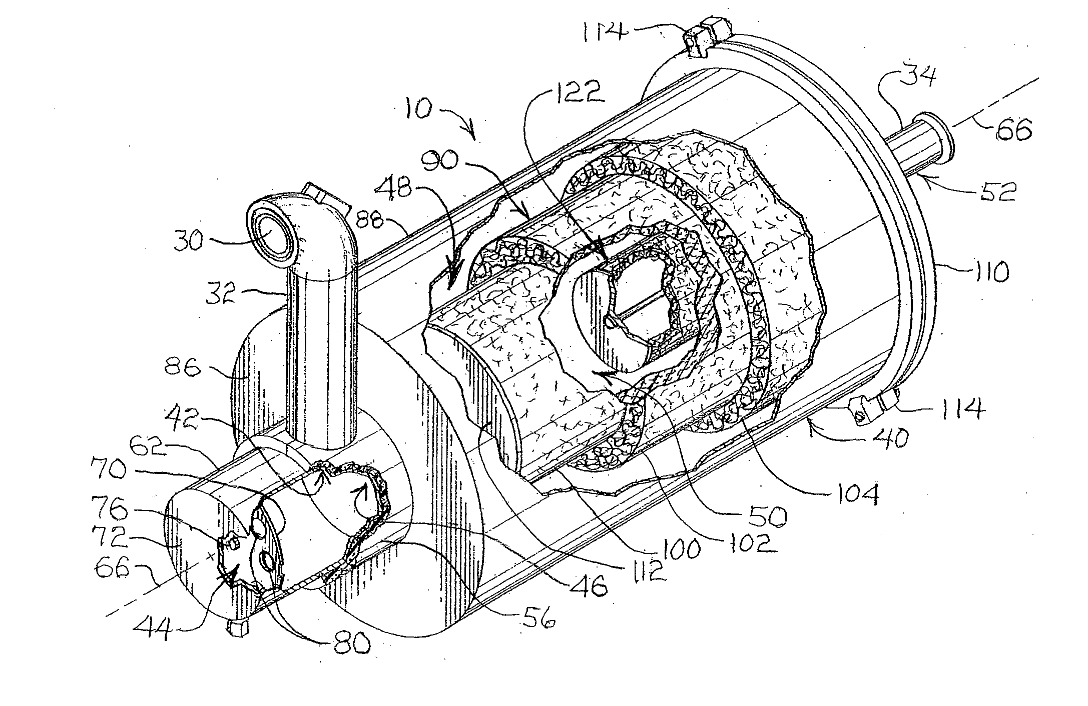
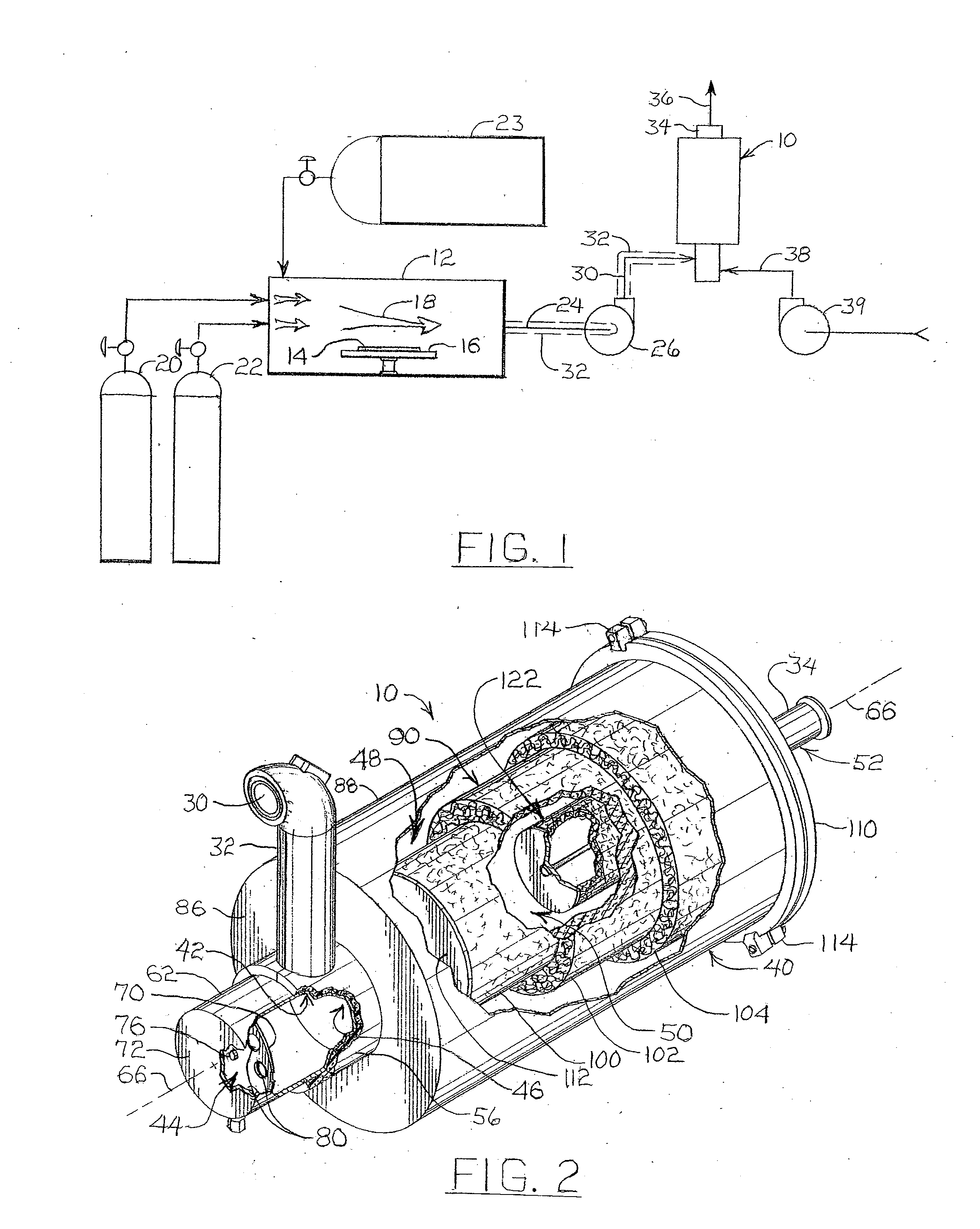
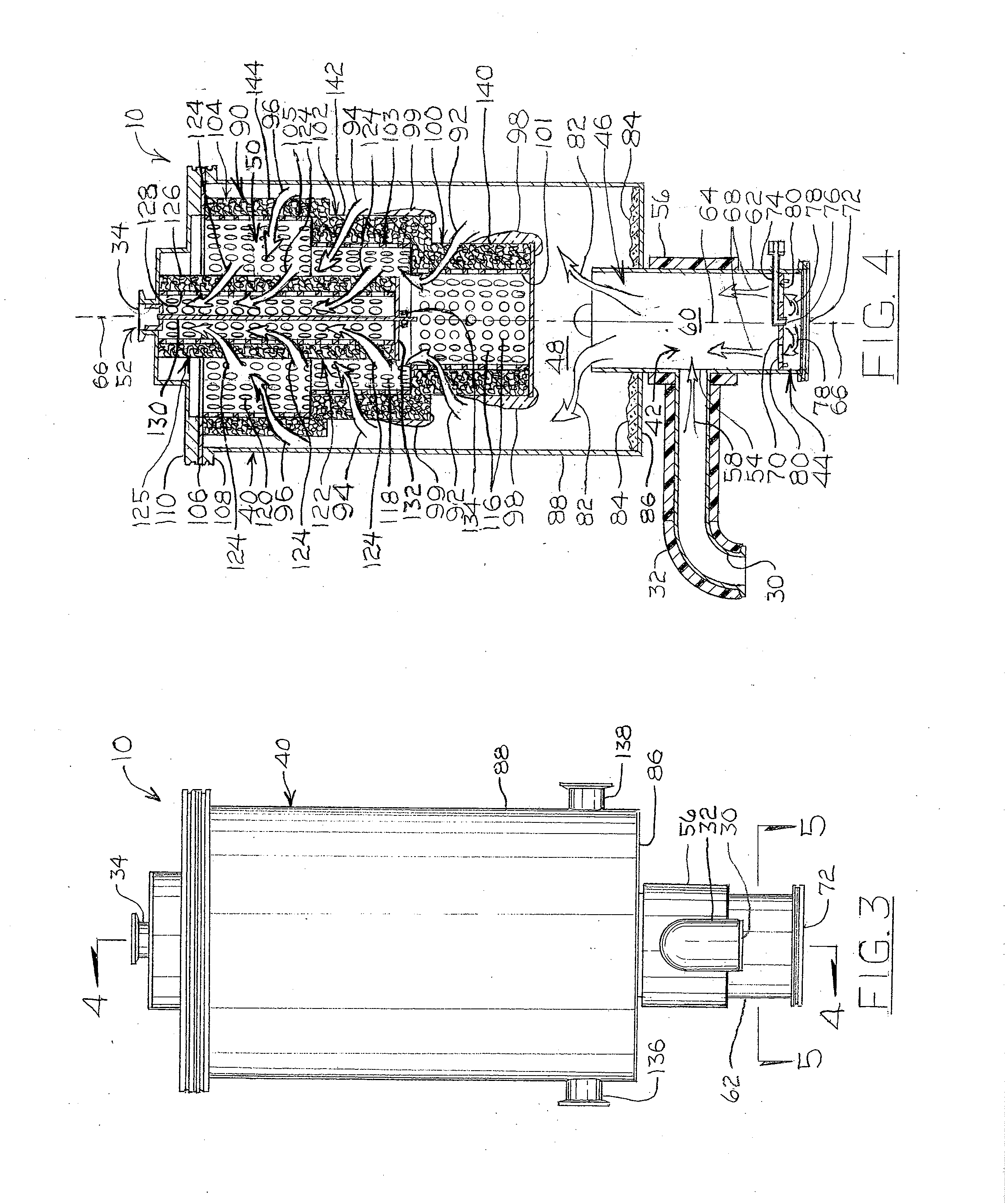
[0053]An example reactive chemical containment device 10 is shown diagrammatically in FIG. 1 in the exhaust system of a typical thin film deposition system as one example implementation of the invention, but recognizing that the invention as recited in the features below can also be implemented in other ways with myriad variations in details, once the principles of the invention are understood from the description herein. This example implementation of the reactive chemical containment device 10 is shown in the isometric view in FIG. 2 with several visual cut out portions of the exterior housing and external components to reveal internal components for convenience, whereas the side elevation view of the device 10 in FIG. 3 conceals the internal components but provides the visual orientations 4-4 and 5-5 for the cross-sectional views in FIGS. 4 and 5, respectively.

[0054]With reference first to FIG. 1, a typical thin film deposition reaction chamber 12 is shown with a substrate 14 pos...


PUM

PropertyMeasurementUnit
Lengthaaaaaaaaaa
Flow rateaaaaaaaaaa
Diameteraaaaaaaaaa

Abstract

A small scale, but effective, reactive chemical containment system includes apparatus and methods for reaction of process gases exhausted from reaction furnaces with a reactant gas in a non-combustible manner to produce and contain particulate or powder byproducts, thereby removing the process gas from the exhaust gas flow. The apparatus provides process gas inlet, treatment reactive gas diffusion, process gas and treatment reactive gas pre-mixing, primary containment, secondary containment, and outlet zones.

Description

CROSS-REFERENCE TO RELATED APPLICATIONS[0001]This invention features the benefit of U.S. provisional application No. 61 / 140,609, filed on Dec. 23, 2008.BACKGROUND OF THE INVENTION[0002]1. State of the Prior Art[0003]The present invention is related to methods and apparatus for capturing and retaining reactive chemical constituents of industrial processes that do not get reacted in thin-film semiconductor deposition reaction chambers, including, but not limited to, wet and dry scrubbers, traps, catch pots, and reactors.[0004]2. State of the Art[0005]Myriad thin film deposition systems, including those used for depositing thin films of a variety of semiconductor materials on substrates or devices, use selected reactive process gases to cause chemical reactions in reaction chambers that result in deposition of a desired thin film material on the substrate or device. In such systems, it is typical to feed and flow more of the reactive process gas or gases into and through the reaction c...

Claims


Application Information

Patent Timeline
IPC IPC(8): B01D53/34B01D50/00B01J12/00B01F23/10
CPCB01D53/76B01D2251/102B01D2251/11B01D2257/204B01D2258/0216B01F3/02B01F5/0682B01F5/0688B01F5/0692B01F5/0693B01F5/0694C23C16/4412Y02C20/30B01F23/10B01F25/45221B01F25/45231B01F25/4523B01F25/45B01F25/4521C23C16/44
Inventor GU, YOUFANDOZORETZ, PAUL
Owner MKS INSTR INC
Why Eureka
Try Eureka