Honeycomb filter for clarifying exhaust gases

Inactive Publication Date: 2005-07-14
IBIDEN CO LTD
View PDF92 Cites 183 Cited by
  • Summary
  • Abstract
  • Description
  • Claims
  • Application Information

AI Technical Summary

Benefits of technology

[0017] The present invention is made to solve the above-mentioned problems, and its object is to provide a honeycomb filter for purifying exhaust gases that is free from

Problems solved by technology

In recent years, particulates (fine particles), contained in exhaust gases that are discharged from internal combustion engines of vehicles, such as buses, trucks and the like, and construction machines, have raised serious problems as these particles are harmful to the environment and the human body.
As such a purifying process for exhaust gases progresses, particulates are gradually accumulated on the partition wall portion that separates the through holes of the honeycomb filter to cause clogging and the subsequent interruption in gas permeability.
For this reason, in the honeycomb filter of this type, a great thermal stress is exerted between a plug and a portion of the partition wall contacting the plug due to a difference between the coefficient of thermal expansion of the columnar body and the coefficient of thermal expansion of the plug during a firing process upon manufacturing, with the result that a gap tends to occur between a plug and a partition wall and cracks tend to occur in the plug and a portion of the partition wall contacting the plug.
However, even in the case where no gap occurs between the plug and the partition wall and when no crack occurs in the plug and the portion of the partition wall contacting the plug upon manufacturing a honeycomb filter, when exhaust gas purifying processes are carried out by using such a honeycomb filter, thermal stresses, caused by the difference between the coefficient of thermal expansion of this columnar body and the coefficient of thermal expansion of the plug, are accumulated between the plug of the honeycomb filter and the portion of the partition wall contacting the plug through thermal cycles that are repeatedly applied due to high-temperature exhaust gases and heating applied during regenerating processes and the like of the honeycomb filter; thus a gap ten

Method used


Image

  • Honeycomb filter for clarifying exhaust gases
  • Honeycomb filter for clarifying exhaust gases
  • Honeycomb filter for clarifying exhaust gases

Examples


example 1

[0179] (1) Powder of α-type silicon carbide having an average particle size of 10 μm (60% by weight) and powder of β-type silicon carbide having an average particle size of 0.5 μm (40% by weight) were wet-mixed, and to 100 parts by weight of the resulting mixture were added and kneaded, 5 parts by weight of an organic binder (methyl cellulose) and 10 parts by weight of water to prepare a material paste.

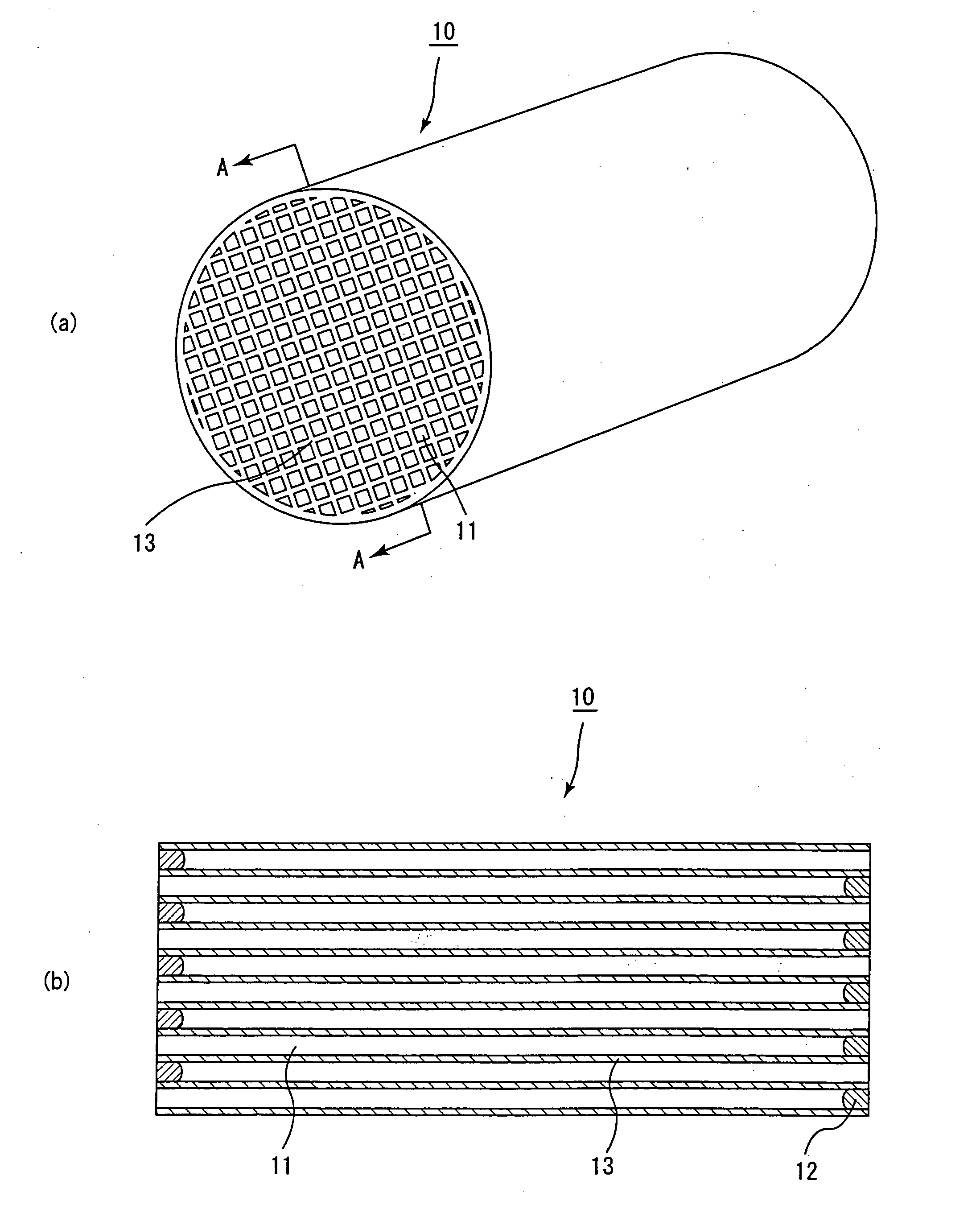
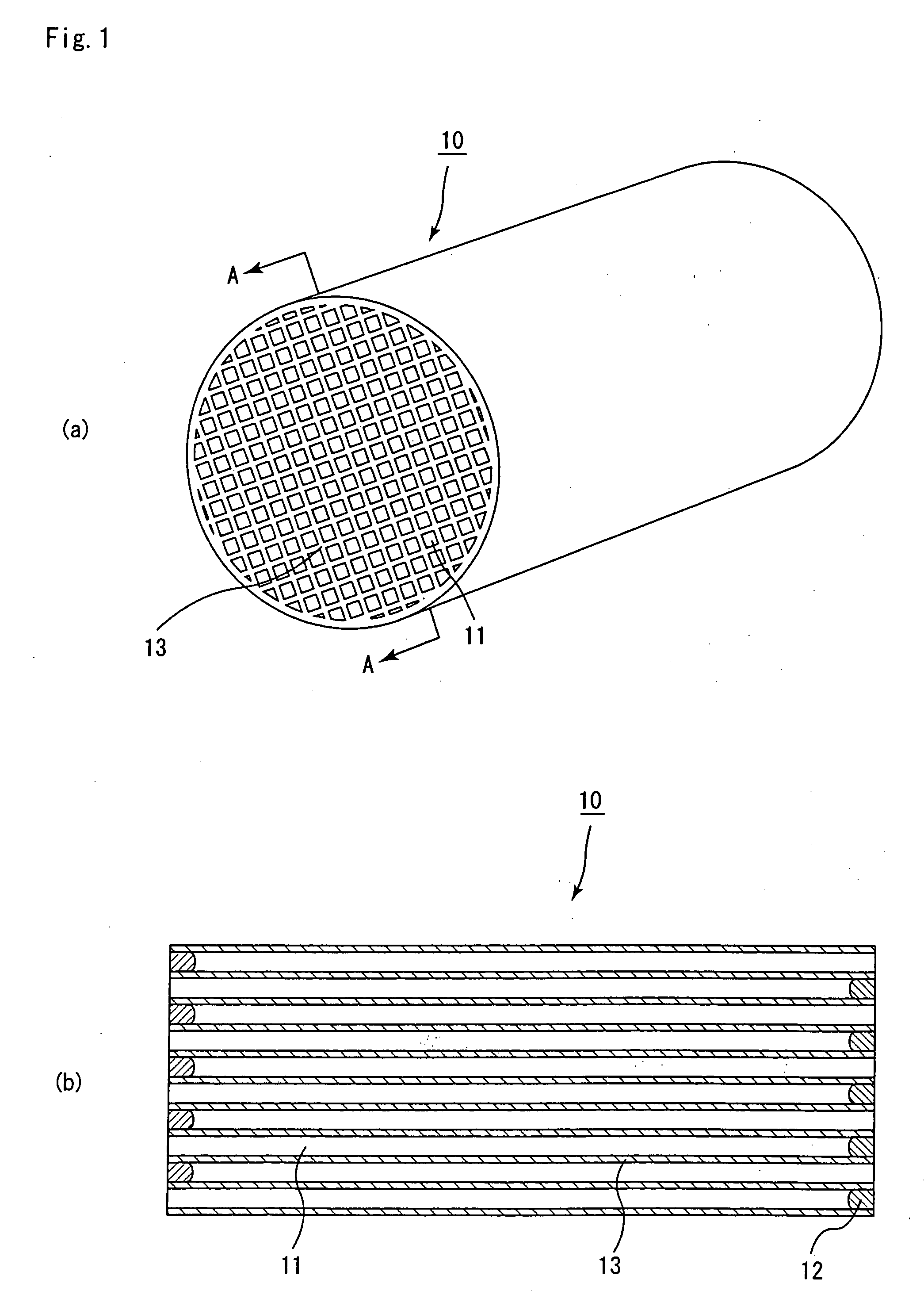
[0180] Next, the above-mentioned material paste was loaded into an extrusion-molding machine, and extruded at an extruding rate of 10 cm / min so that a ceramic formed body having almost the same shape as the porous ceramic member 30 shown in FIG. 3 was formed, and the ceramic formed body was dried by using a microwave dryer to prepare a ceramic dried body.

[0181] Next, powder of α-type silicon carbide having an average particle size of 10 μm (60% by weight) and powder of β-type silicon carbide having an average particle size of 0.5 μm (40% by weight) were wet-mixed, and to 100 parts b...

example 2

[0190] The same processes as those of Example 1 were carried out except that a filler paste, which had been prepared by wet-mixing powder of α-type silicon carbide having an average particle size of 10 μm (60% by weight) and powder of β-type silicon carbide having an average particle size of 0. 5 μm (40% by weight), and adding, to 100 parts by weight of the resulting mixture, 2 parts by weight of UNILOOP, 8 parts by weight of OX-20, 1.1 parts by weight of PLYSURF, 4 parts by weight of Binder D and 0.2 parts by weight of acrylic particles so as to be evenly mixed, was used to manufacture a honeycomb filter.

[0191] In the honeycomb filter according to Example 2, thus manufactured, the columnar body except for the plug had an average pore diameter of 10 μm with a porosity of 20%, and the plug had a porosity of 5%; thus, the porosity of the plug was 0.25 times as much as the porosity of the columnar body.

example 3

[0192] The same processes as those of Example 1 were carried out except that a filler paste, which had been prepared by wet-mixing powder of α-type silicon carbide having an average particle size of 10 μm (60% by weight) and powder of β-type silicon carbide having an average particle size of 0.5 μm (40% by weight), and adding, to 100 parts by weight of the resulting mixture, 4 parts by weight of UNILOOP, 11 parts by weight of OX-20, 2 parts by weight of PLYSURF, 5 parts by weight of Binder D and 10 parts by weight of acrylic particles so as to be evenly mixed, was used to manufacture a honeycomb filter.

[0193] In the honeycomb filter according to Example 3, thus manufactured, the columnar body except for the plug had an average pore diameter of 10 μm with a porosity of 20%, and the plug had a porosity of 30%; thus, the porosity of the plug was 1.5 times as much as the porosity of the columnar body.


PUM

PropertyMeasurementUnit
Fractionaaaaaaaaaa
Fractionaaaaaaaaaa
Densityaaaaaaaaaa

Abstract

An object of the present invention is to provide a honeycomb filter for purifying exhaust gases that is free from a gap formed between a plug and a partition wall and cracks generated in the plug and a portion of the partition wall contacting the plug, and is superior in durability. The present invention provides a honeycomb filter for purifying exhaust gases which has a structure in which: a columnar body made of porous ceramic comprises a number of through holes, said through holes being placed in parallel with one another in the length direction with a wall portion interposed therebetween; predetermined through holes of said through holes are filled with plugs at one end of said columnar body, while the through holes that have not been filled with said plugs at said one end are filled with plugs at the other end of said columnar body; and a part or all of said wall portion functions as a filter for collecting particulates, wherein the porosity of the columnar body is in a range from 20 to 80%, and the porosity of the plug is 90% or less and is also set to 0.15 to 4.0 times as much as the porosity of the columnar body.

Description

CROSS REFERENCE TO RELATED APPLICATION [0001] This application claims benefit of priority to Japanese Patent Application No. 2002-109717, filed on Apr. 11, 2002, the contents of which are incorporated by reference herein. TECHNICAL FIELD [0002] The present invention relates to a honeycomb filter for purifying exhaust gases that is used as a filter for removing particulates and the like contained in exhaust gases discharged from an internal combustion engine such as a diesel engine or the like. BACKGROUND ART [0003] In recent years, particulates (fine particles), contained in exhaust gases that are discharged from internal combustion engines of vehicles, such as buses, trucks and the like, and construction machines, have raised serious problems as these particles are harmful to the environment and the human body. [0004] For this reason, there have been proposed various ceramic filters that allow exhaust gases to pass through porous ceramics and collect particulates in the exhaust gas...

Claims


Application Information

Patent Timeline
IPC IPC(8): B01D53/94B01J35/04C04B37/00F01N3/021F01N3/022F01N3/023F01N3/035F01N3/28F01N13/04F01N13/18
CPCB01D53/9454Y10T428/24149F01N3/0222F01N3/023F01N3/035F01N13/1888F01N2330/06F01N2330/14F01N2330/48F01N2450/28F01N2510/065Y02T10/20Y02T10/22F01N13/017Y10T428/24157B01J35/04Y02T10/12
Inventor YAMADA, KEIJI
Owner IBIDEN CO LTD
Why Eureka
Try Eureka