
Honeycomb structured body, method for manufacturing honeycomb structured body and exhaust gas purifying device

a technology of structured body and honeycomb, which is applied in the direction of machines/engines, chemical/physical processes, domestic applications, etc., can solve the problems of contaminant harmful to the environment and the human body

Active Publication Date: 2007-06-07
IBIDEN CO LTD
View PDF51 Cites 183 Cited by
  • Summary
  • Abstract
  • Description
  • Claims
  • Application Information

AI Technical Summary

Benefits of technology

The present invention relates to a honeycomb structured body comprising a plurality of porous ceramic members joined by an adhesive layer. The ceramic members have cells with a cell wall and a filling body that fills in the corners of the cells. The ceramic members have an outer edge wall that is thicker than the cell wall. The ceramic members can be sealed at the ends. The honeycomb structured body has a cross-sectional shape with an almost tetragon and an almost right triangle. The ceramic members have an aperture ratio of the cells of at least 60%. The thickness of the outer edge wall is at least about 0.1 mm and at most about 0.4 mm. The honeycomb structured body can support a catalyst. The technical effects of the invention include improved mechanical strength, increased cell wall thickness, and improved cell corner design.

Problems solved by technology

Recently, particulate matters (fine particles, hereinafter referred to as PM) such as soot, contained in exhaust gases that are discharged from internal combustion engines for vehicles such as a bus, a truck, construction equipment and the like, have raised problems as contaminants harmful to the environment and the human body.

Method used


Image

  • Honeycomb structured body, method for manufacturing honeycomb structured body and exhaust gas purifying device
  • Honeycomb structured body, method for manufacturing honeycomb structured body and exhaust gas purifying device
  • Honeycomb structured body, method for manufacturing honeycomb structured body and exhaust gas purifying device

Examples


example 1

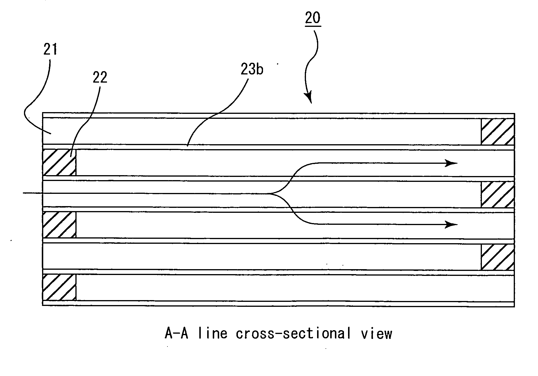
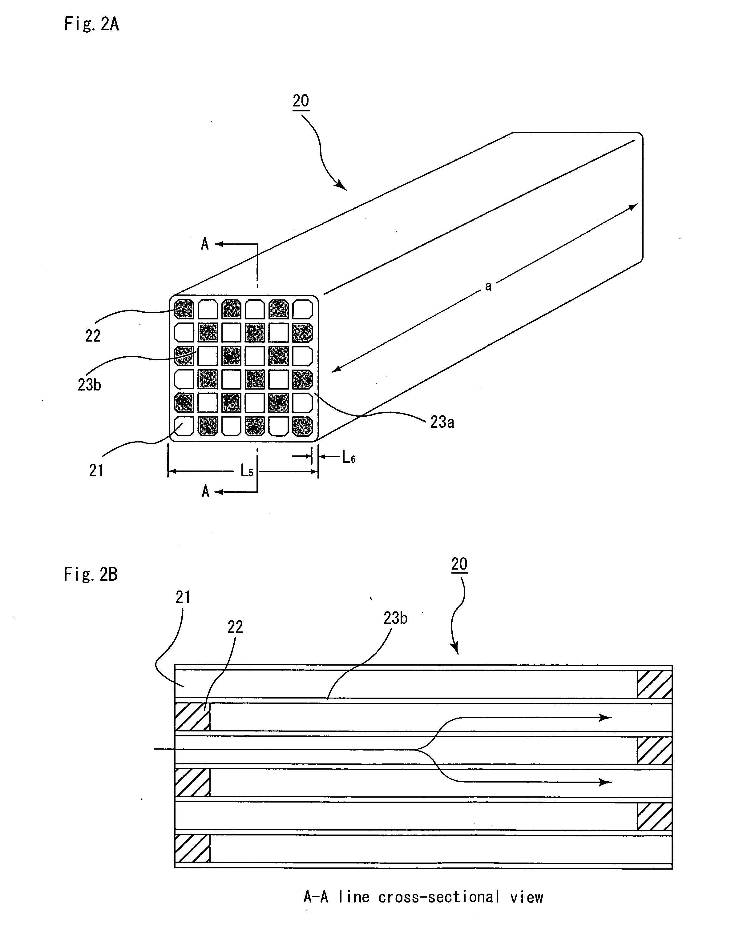
[0245] An α-type silicon carbide powder having an average particle diameter of 22 μm (hereinafter referred to as SiC coarse powder) (6000 parts by weight), 2570 parts by weight of an α-type silicon carbide powder having an average particle diameter of 0.5 μm (hereinafter referred to as SiC fine powder), 700 parts by weight of an organic binder (methyl cellulose), 300 parts by weight of a pore forming agent (acrylic resin) having an average particle diameter of 20 μm with pores formed therein, 330 parts by weight of a lubricant (UNILUB, manufactured by NOF Corp.), 150 parts by weight of glycerin, and an appropriate amount of water were blended and evenly mixed to prepare a mixed material composition. This mixed composition was charged into an extrusion molding apparatus, and extrusion molded to manufacture a raw molded body in which corner portions of cells are provided with a filling body as shown in FIG. 2, and the corner portion of the molded body had the shape of a R-chamfered co...

examples 2 to 9

[0253] The same processes as those of Example 1 were carried out to manufacture a honeycomb structured body, except that the structure of the porous ceramic members, aperture ratio, thickness of cell walls, thickness of outer edge walls, cell density or ratio of the length of one side of a filling body to the length of one side of a cell before forming the filling body (hereinafter, referred to as ratio of one side of a filling body) was changed as shown in Tables 1 and 2. Here, when the outer corner was formed into a shape of a chamfered corner, the shape of the chamfered corner was a shape of a R-chamfered corner as in Example 1.


PUM

PropertyMeasurementUnit
thicknessaaaaaaaaaa
thicknessaaaaaaaaaa
thicknessaaaaaaaaaa

Abstract

A honeycomb structured body in which a plurality of porous ceramic members are combined with one another by interposing an adhesive layer, each of the porous ceramic members having a plurality of cells placed in parallel with one another in a longitudinal direction with a cell wall therebetween and having an outer edge wall on the outer edge surface thereof, wherein each of the porous ceramic members has a filling body which is provided so as to fill in at least one corner portion of at least one outermost cell of the porous ceramic members, a cross-sectional shape of the outermost cell at the face orthogonal to the longitudinal direction of the cells is an almost tetragon, and a cross-sectional shape of the filling body at the face orthogonal to the longitudinal direction of the cells is an almost right triangle.

Description

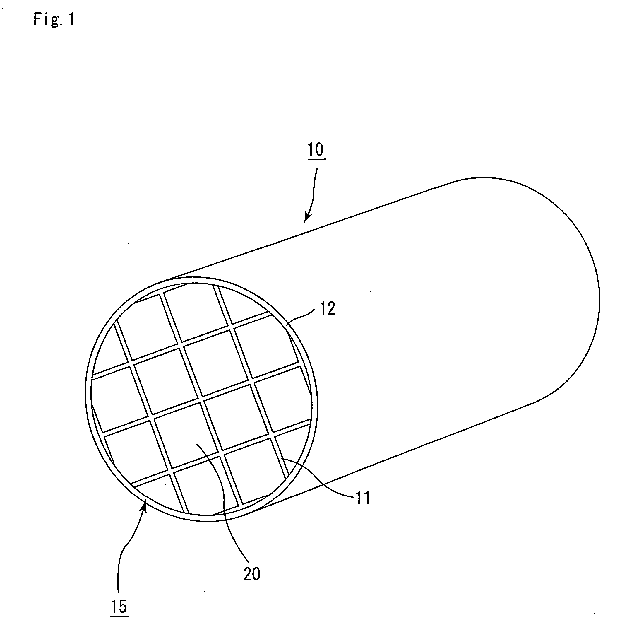
CROSS-REFERENCE TO RELATED APPLICATIONS [0001] This application claims benefit of priority based on Japanese Patent Application No. 2005-334782 filed on Nov. 18, 2005, and PCT / JP2006 / 316636, filed on Aug. 24, 2006. The contents of these applications are incorporated herein by reference in their entirety.BACKGROUND OF THE INVENTION [0002] 1. Field of the Invention [0003] The present invention relates to a honeycomb structured body, a method for manufacturing a honeycomb structured body, and an exhaust gas purifying device. [0004] 2. Discussion of the Background [0005] Recently, particulate matters (fine particles, hereinafter referred to as PM) such as soot, contained in exhaust gases that are discharged from internal combustion engines for vehicles such as a bus, a truck, construction equipment and the like, have raised problems as contaminants harmful to the environment and the human body. [0006] In order to solve those problems, there have been proposed various applications in whi...

Claims


Application Information

Patent Timeline
Patent Type & Authority Applications(United States)
IPC IPC(8): B32B3/12C04B33/32
CPCB01D2046/2496B01D46/2455B01D46/2466B01D46/0001B01D46/2459C04B2111/00793F01N3/0222F01N2330/322B01D2046/2481B01D46/2451F01N2330/34B01D46/2474B01D2046/2477F01N2330/323B01D46/247B01J35/04Y02T10/20Y10T428/24149C04B38/008C04B35/00C04B38/0003C04B38/0006Y02T10/12B01D46/2488B01D46/249B01D46/2498B01D46/2484B01D46/2482B01D46/2478B01J35/56B01D39/00B01D46/2462
Inventor SAKAGUCHI, HIROSHIOHNO, KAZUSHIGE
Owner IBIDEN CO LTD
Learn More