

Honeycomb filter for clarification of exhaust gas
a technology of exhaust gas and honeycomb, which is applied in the direction of filtration separation, machine/engine, separation process, etc., can solve the problems of affecting the quality of exhaust gas, so as to achieve the effect of superior durability
- Summary
- Abstract
- Description
- Claims
- Application Information
AI Technical Summary
Benefits of technology
Problems solved by technology
Method used
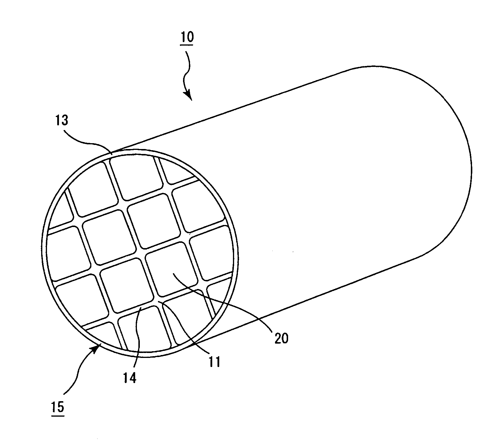
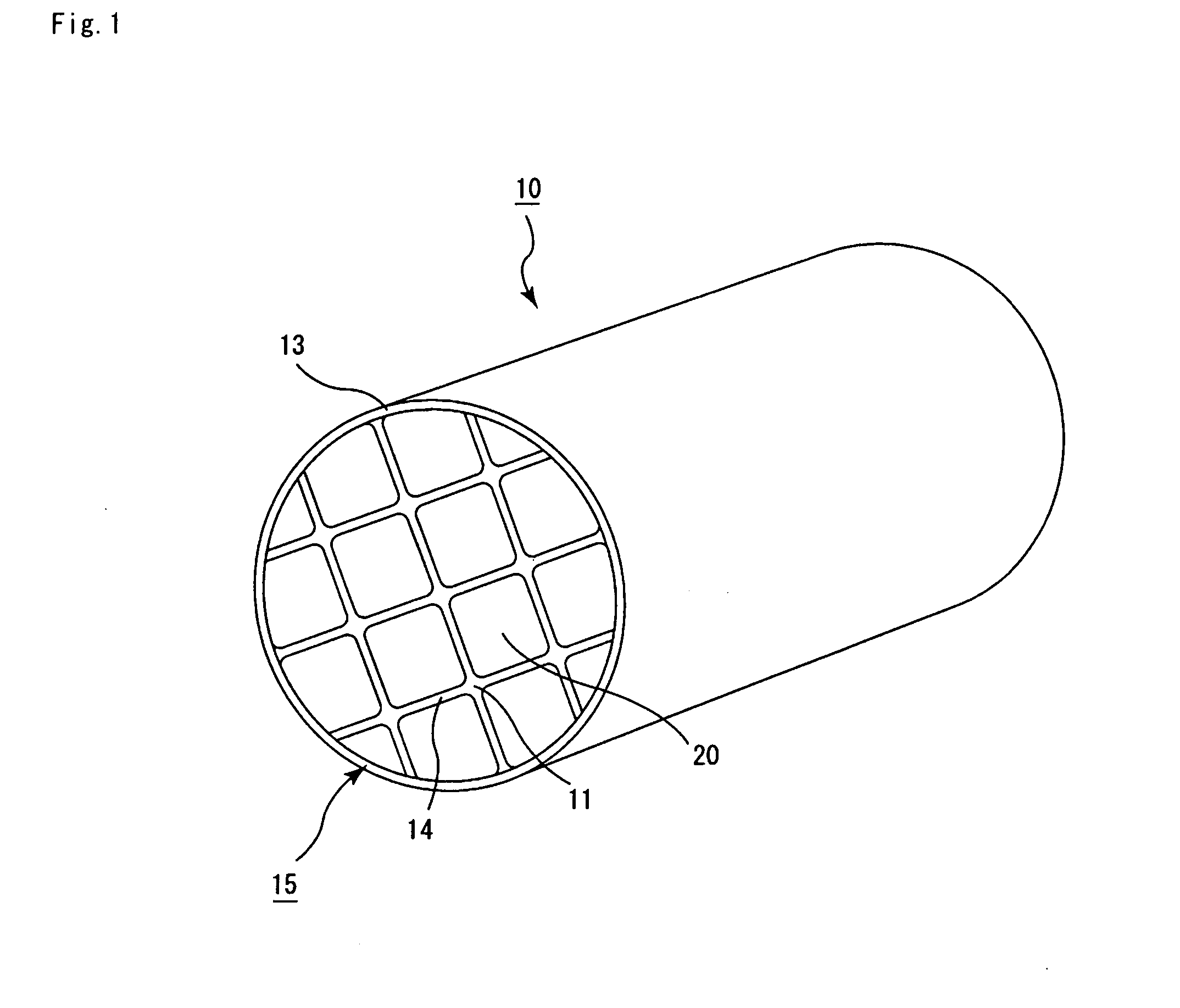
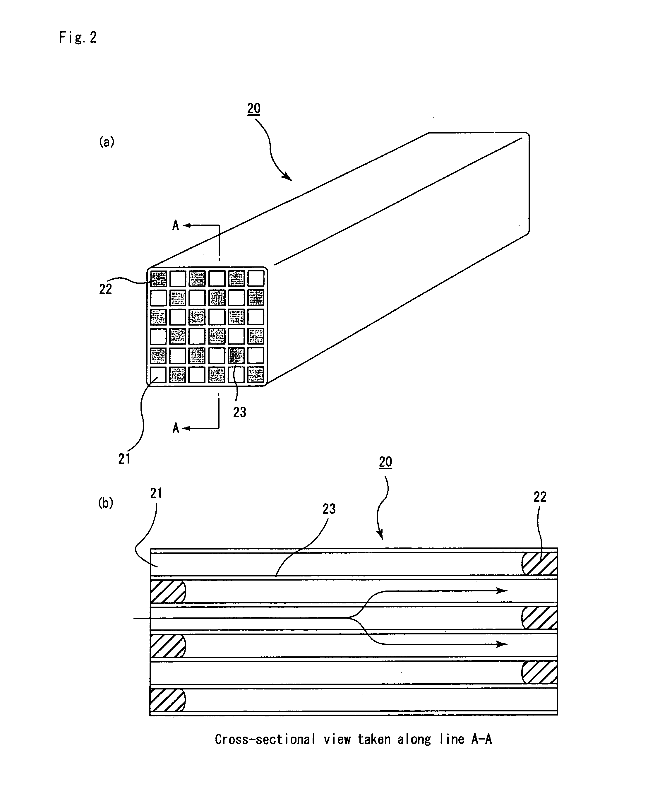
Image

Examples
example 1
(EXAMPLE 1)
[0155] (1) Powder of α-type silicon carbide having an average particle size of 5 μm (60% by weight) and powder of β-type silicon carbide having an average particle size of 0.5 μm (40% by weight) were wet-mixed, and to 100 parts by weight of the resulting mixture were added and kneaded 5 parts by weight of an organic binder (methyl cellulose) and 10 parts by weight of water to obtain a mixed composition. Next, after a slight amount of a plasticizer and a lubricant have been added and kneaded therein, the resulting mixture was extrusion-molded so that a raw formed body was manufactured.
[0156] Next, the above-mentioned raw formed body was dried by using a microwave drier to form a ceramics dried body, and R-chamfered faces are formed by cutting corner portions of the circumference of this ceramics dried body so that each of the corner portions is allowed to have an R face of R=0.0059 mm.
[0157] Thereafter, predetermined through holes were then filled with a paste having the...
examples 2 to 15
(EXAMPLES 2 TO 15, COMPARATIVE EXAMPLES 1 TO 6)
[0163] The same processes as (1) of Example 1 were carried out except that the size of the chamfered face R formed on each of the corner portions of the circumference of the ceramics dried body was set to each of values shown in Table 1 so that a porous ceramic member was manufactured.
[0164] The same processes as (2) of Example 1 were carried out except that the above-mentioned porous ceramic member was used and that the thickness of the sealing material layer formed between the porous ceramic members was set to each of values as shown in Table 1 so that a honeycomb filter was manufactured.
[0165] The cross-sectional shape of the ceramic block for each of the honeycomb filters according to Examples 2 to 15 was almost the same as that shown in FIG. 3(a) . Here, on the end face of the ceramic block, the maximum width L of each crisscross portion of the sealing material layer formed between the porous ceramic members, the minimum width l ...
example 16
(EXAMPLE 16)
[0176] The same processes as Example 1 were carried out except that upon forming a ceramic block, instead of combining 5 (in longitudinal direction)×5 (in lateral direction) porous ceramic members with one another so as to be cut into a cylindrical shape, 3 (in longitudinal direction)×6 (in lateral direction) porous ceramic members 3 were combined with one another to form an elliptical columnar shape with a major diameter of 198 mm and a minor diameter of 99 so that a honeycomb filter having an elliptical columnar shape was manufactured.
[0177] The cross-sectional shape of the ceramic block for the honeycomb filter according to Example 16 was almost the same as that shown in FIG. 3(a). Here, on the end face of the ceramic block, the maximum width L of each crisscross portion of the sealing material layer formed between the porous ceramic members was 0.15 mm, the minimum width l of the sealing material layer was 0.10 mm, and the maximum width L of the crisscross portion w...
PUM
| Property | Measurement | Unit |
|---|---|---|
| size | aaaaa | aaaaa |
| size | aaaaa | aaaaa |
| size | aaaaa | aaaaa |
Abstract
Description
Claims
Application Information