Electronic paper display system

a display system and electronic paper technology, applied in typewriters, printing, instruments, etc., can solve the problems of resource listing and insufficient management of information

Inactive Publication Date: 2006-01-26
PANASONIC CORP
View PDF3 Cites 186 Cited by
  • Summary
  • Abstract
  • Description
  • Claims
  • Application Information

AI Technical Summary

Problems solved by technology

However, in the above example that is to output information on a paper from the conventional printer, it is thought that a 25% portion of the output results in garbage on the same day thus having a problem of resource listing.
Thus, there is a problem that information is to be managed insufficient.

Method used


Image

  • Electronic paper display system
  • Electronic paper display system
  • Electronic paper display system

Examples


embodiment 1

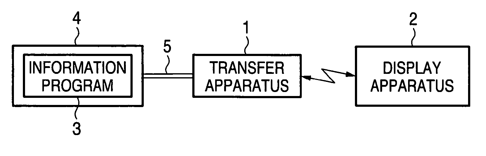
[0087]FIG. 1 is an arrangement diagram of an electronic paper display system in embodiment 1 of the invention. In FIG. 1, 1 is a transfer apparatus, 2 is display apparatus, 4 is PC for installing an information program 3 thereon, and 5 is a cable. Transfer apparatus 1 is connected to PC by cable 5. Meanwhile, transfer apparatus 1 and display apparatus 2 are wirelessly connected with each other. Incidentally, PC4 and transfer apparatus 1 in this embodiment are connected by the cable but can be connected wirelessly by such means as a wireless LAN.

[0088] The present system basically enables to output the information prepared in PC to predetermined display apparatus 2 by way of transfer apparatus 1. With reference to FIGS. 3 to 7, explanation is now made in detail on the operation of the basic system shown in FIG. 1.

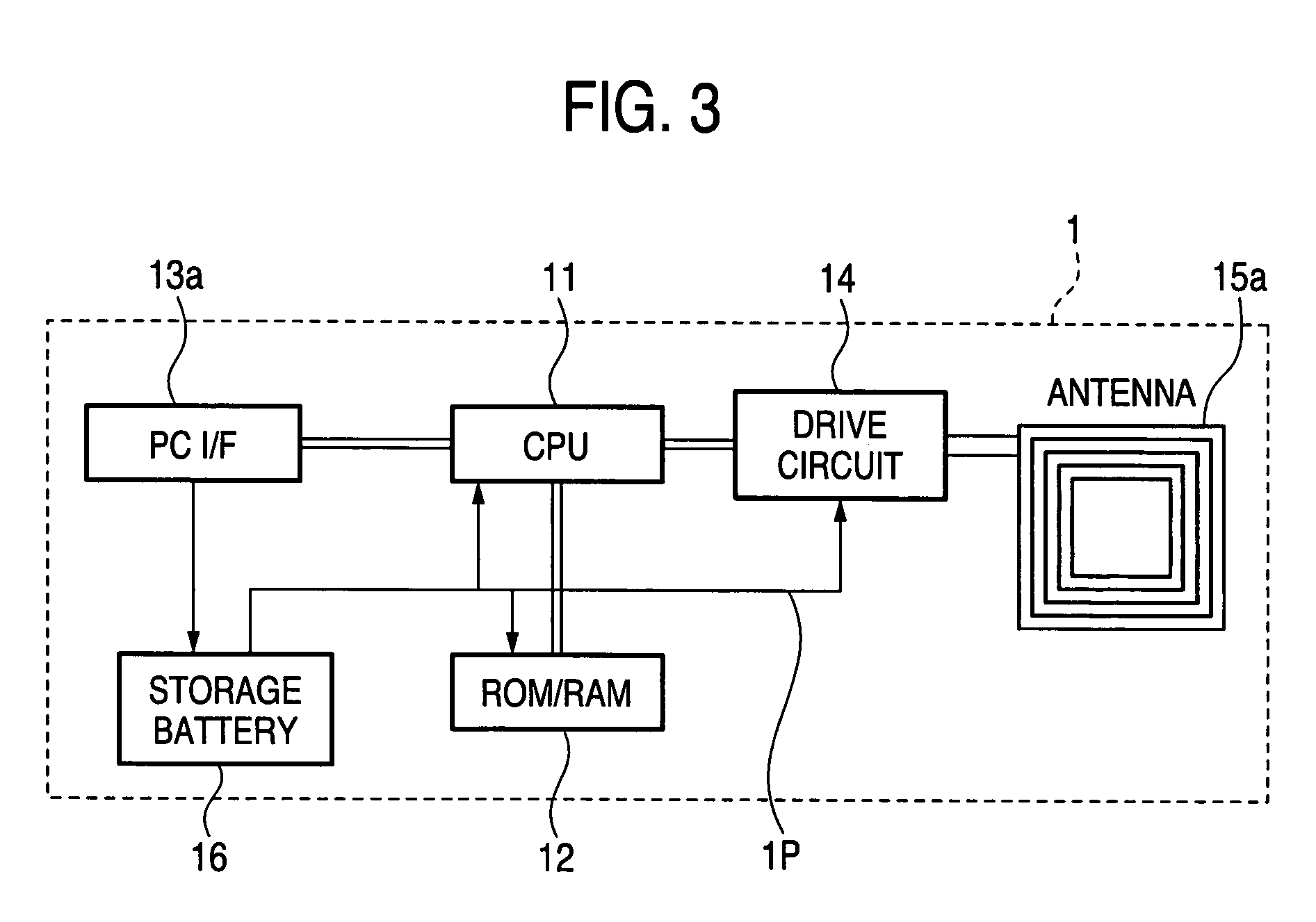
[0089]FIG. 3 is an interior block diagram of the transfer apparatus in embodiment 1 of the invention, wherein 11 is a CPU, 12 is a ROM / RAM as storage means, 13a is an PC I...

embodiment 2

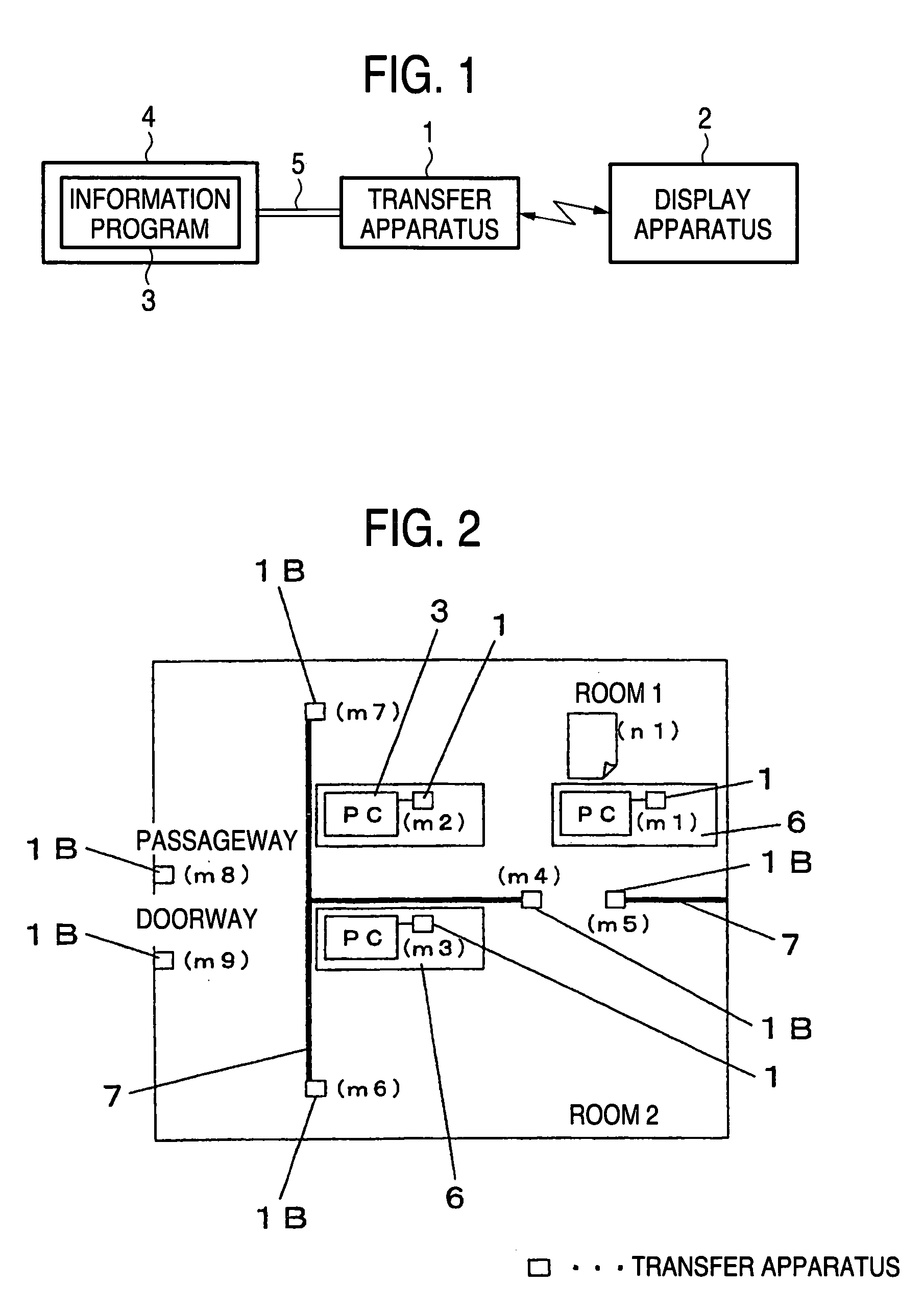
[0113]FIG. 2 is an arrangement diagram of an electronic paper display system in embodiment 2 of the invention. In FIG. 2, the same constituent elements as those of FIGS. 1 and 3 to 7(b) are attached with the same references, to omit the explanations thereof.

[0114]FIG. 2 shows a complex system arrangement using an electronic paper display system arranging a plurality of transfer apparatuses 1 and PCs 4 within a room. In FIG. 2, 6 is a table for resting the PC and transfer apparatus 1 thereon, 7 is a wall partitioning the room, 1B is another form of transfer apparatus 1 which is a connection apparatus having a function of wireless connection to a network, thus constituting an electronic paper display system.

[0115] PC 4 connected with transfer apparatus 1 is installed thereon with an information program 3. Note that one information program 3 serves as a master administrating the overall whereas the others are to operate under the dominance thereof by taking an association with the in...

embodiment 3

[0126]FIG. 9 is an interior block diagram of a display apparatus in embodiment 3 of the invention. In FIG. 9, the same constituent elements as those of FIG. 4 are attached with the same references, to omit the explanations thereof. In display device 2 in FIG. 9, write to the electronic paper is by being sandwiched between two surfaces thereby enabling a recording by surface-based writing. In FIG. 9, 27A connected to a record control circuit 28 is a recording surface while 201 is an electrode sheet. Those constitute a recording section to the electronic paper 200a. Incidentally, the section 2B surrounded by broken line is a circuit of other than the display section, which can be made as one-chip IC. Accordingly, utilization is by placing the electronic paper 200a on the recording surface 27A of display apparatus 2 in a state sandwiched by a light-transmissive electrode sheet 201 arranging a transparent electrode over the entire surface.

[0127]FIG. 10(a) is a sectional view of an elec...


PUM


Abstract

It is an object to provide an electronic paper display system capable of communicating in non-contact with an electronic paper by transfer apparatus and managing information by use of an electronic paper high in illegibility and portability as a medium of information display. An electronic paper display system that communication is made with display apparatus 2 having an electronic paper and wireless tag from transfer apparatus 1 capable of accessing a PC or a network, to perform a personal identification, based on which display information is transferred. Meanwhile, by transfer apparatuses 1 arranged in plurality in a space, the electronic paper is detected to manage information.

Description

BACKGROUND OF THE INVENTION [0001] 1. Field of the Invention [0002] The present invention relates to an electronic paper display system for generating and managing information by utilization of an electronic paper high in illegibility / portability and easy to manage information. [0003] 2. Description of the Related Art [0004] Conventionally, there are those of a form for personal use that, when to look electronic information by the paper output high in illegibility and portability, the information is instructed for printing from a personal computer (hereinafter, abbreviated as PC) to a PC or to a printer connected to a network to thereby form an image on a paper or an electronic paper as a display device by means of the printer (see JP-A-2003-333001, for example). [0005] Meanwhile, where to personally use the information existing in an image form on a paper, there are those of a form for copying by the copier or changing a scanner readout into electronic information so that it can be...

Claims


Application Information

Patent Timeline
Patent Type & Authority Applications(United States)
IPC IPC(8): G09G3/00
CPCG09G2380/06G09G2380/14B41J3/4076B41J3/46G06F3/1454G09G2380/04G09G5/006G09G2300/08G09G2370/042G09G2370/16G09G2380/02G09G3/344
Inventor OGAWA, TOSHIYUKIKITADA, TAKASHISAKAI, HIROAKI
Owner PANASONIC CORP
Why Eureka
Try Eureka