Flame quality sensor

a quality sensor and sensor technology, applied in the field of flame quality sensors, can solve the problems of improper burning of flames, increased pollution, and low heating efficiency, and achieve the effects of reducing the amount of generated pollution, reducing the efficiency of combustion, and improving the quality of combustion

Inactive Publication Date: 2006-01-26
AVAGO TECH ECBU IP (SINGAPORE) PTE LTD
View PDF5 Cites 4 Cited by
  • Summary
  • Abstract
  • Description
  • Claims
  • Application Information

AI Technical Summary

Problems solved by technology

If the flame used for heat does not get proper oxygen, the flame turns from blue to yellow and a sooty deposit is created that lowers heating efficiency and can increase the amount of generated pollution.
Regular maintenance can detect the existence of an improperly burning flame.
However, in many households, an interval of a year or more can occur between the performance of maintenance.
Thus, a deficiency in operation resulting in a sub-optimal flame can be undetected for a long period of time.
This can increase the cost of operating the appliance as well as result in the production of unnecessary pollution.

Method used


Image

  • Flame quality sensor
  • Flame quality sensor
  • Flame quality sensor

Examples


Embodiment Construction

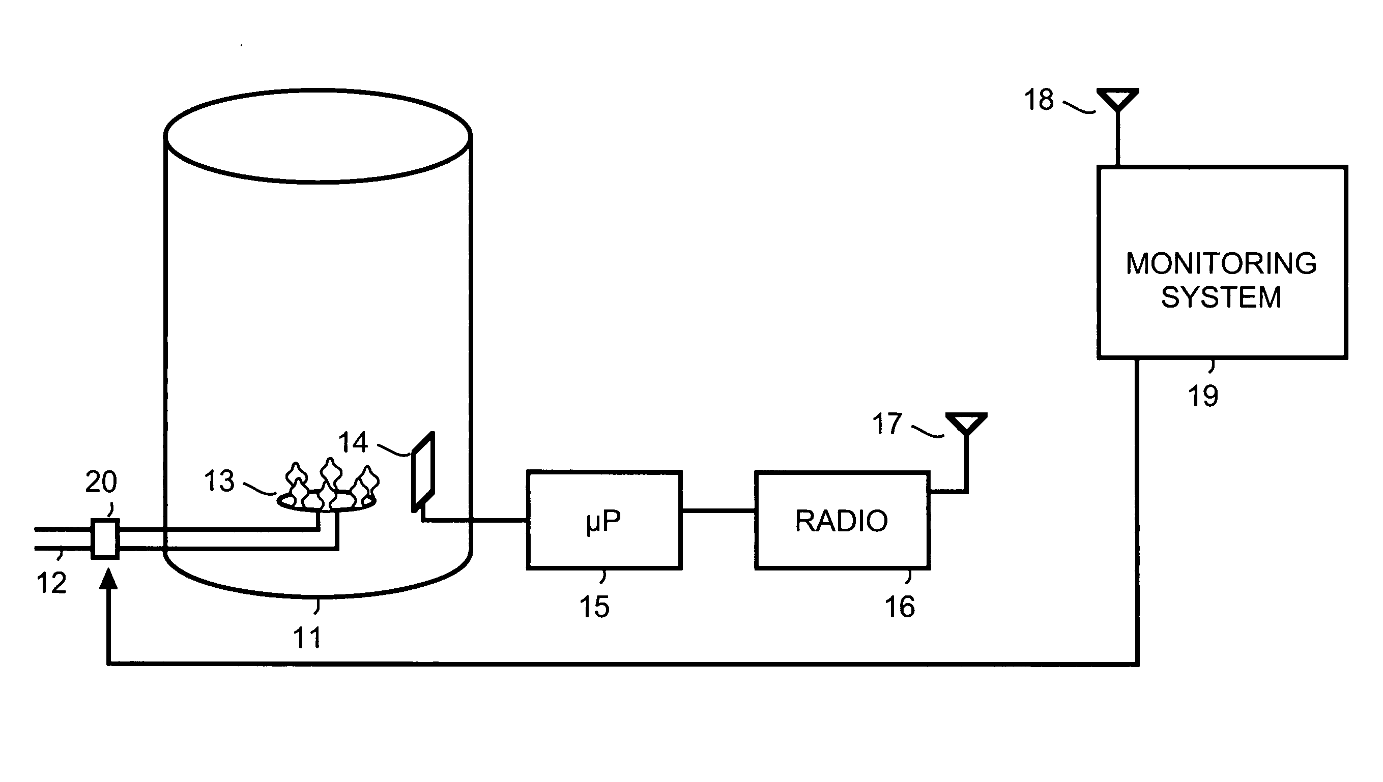
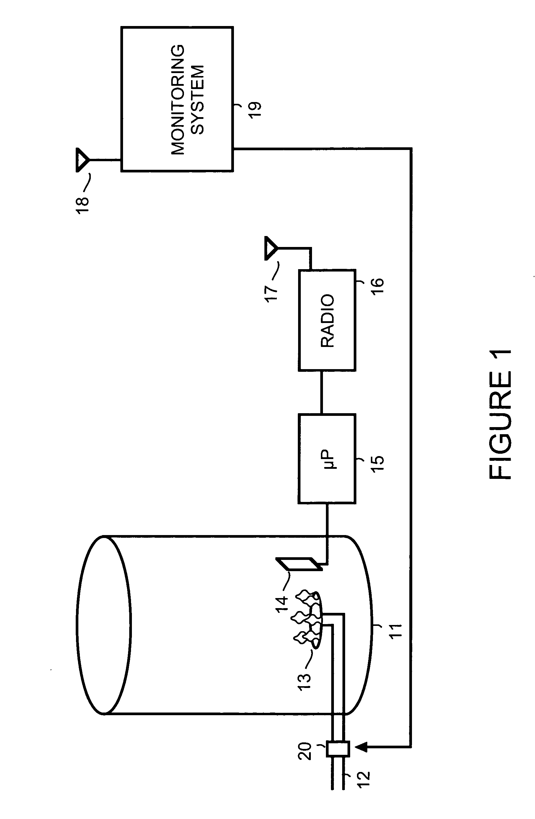
[0007]FIG. 1 is a simplified block diagram showing operation of a flame quality sensor in accordance with an embodiment of the present invention. A flame 13, within an appliance 11, is optically detected by an imager 14. A pipe 12 delivers gas that is fuel for flame 13. For example, appliance 11 is a water heater. Alternatively, appliance 11 is a dryer, a furnace, a broiler, an oven, a refrigerator, an air conditioner or another appliance that uses a flame.

[0008] A microprocessor (μP) 15 is used to process the image received from imager 14. The image produced by imager 14 can include, for example, information about color, brightness, and / or size of flame 13. Microprocessor 15 forwards the image information to a monitoring system 19, for example via a radio 16. For example, radio 16 uses an antenna 17 to transmit information to an antenna 18 of monitoring system 19. Alternatively, microprocessor 15 forwards the image information to a monitoring system 19 via other wireless, electric...


PUM


Abstract

A monitoring device includes an imager, a processor and transmission media. The imager is used to capture visual information pertaining to a flame produced by an appliance. The processor processes the visual information to produce processed information. The transmission media is used by the processor to forward the processed information to a monitoring system.

Description

BACKGROUND [0001] In many applications, natural gas is used to supply fuel for flame in appliances such as water heaters, dryers, broilers, ovens and other appliances. For example, in applications such as recreational vehicles, flame from natural gas is used to produce power for refrigerators and air conditioners. [0002] If the flame used for heat does not get proper oxygen, the flame turns from blue to yellow and a sooty deposit is created that lowers heating efficiency and can increase the amount of generated pollution. [0003] Regular maintenance can detect the existence of an improperly burning flame. However, in many households, an interval of a year or more can occur between the performance of maintenance. Thus, a deficiency in operation resulting in a sub-optimal flame can be undetected for a long period of time. This can increase the cost of operating the appliance as well as result in the production of unnecessary pollution. SUMMARY OF THE INVENTION [0004] In accordance with...

Claims


Application Information

Patent Timeline
Patent Type & Authority Applications(United States)
IPC IPC(8): H04N7/18H04N9/47
CPCF23N5/242F23N2023/08H04N7/183F23N2029/20F23N2031/20F23N2023/38F23N2223/08F23N2223/38F23N2229/20F23N2231/20
Inventor MAHOWALD, PETER H.KEE, PAMELA LAU
Owner AVAGO TECH ECBU IP (SINGAPORE) PTE LTD
Why Eureka
Try Eureka