
Eureka
For R&D, Eureka makes reading and utilizing patents & technical documents easy.
Eureka AIR
Designed for self-driven R&D workflows. Generate viable solutions, solve complex R&D challenges, empower your innovation with AI.

Eureka Materials
Designed for material experts only. Revolutionize your material R&D, from search, analyze, to developing new materials.

TechResearch
Generate reliable direction feasibility study reports for your R&D in just a few steps.

TechSeek
Discover and master advanced knowledge NOW. Basics, ideas, possibilities, all at once.

TechMind
As an expert in R&D Theories, TechMind can generates customized viable solutions instantly.

TechRisk
Analyze your overall solution with one click, know your potential R&D risks in advance.

TechMonitor
Get weekly tech updates, stay abreast of the latest tech innovations and key insights.
Image pick-up apparatus and image restoration method
- Summary
- Abstract
- Description
- Claims
- Application Information
AI Technical Summary
Benefits of technology
Problems solved by technology
Method used
Image

Examples
first embodiment
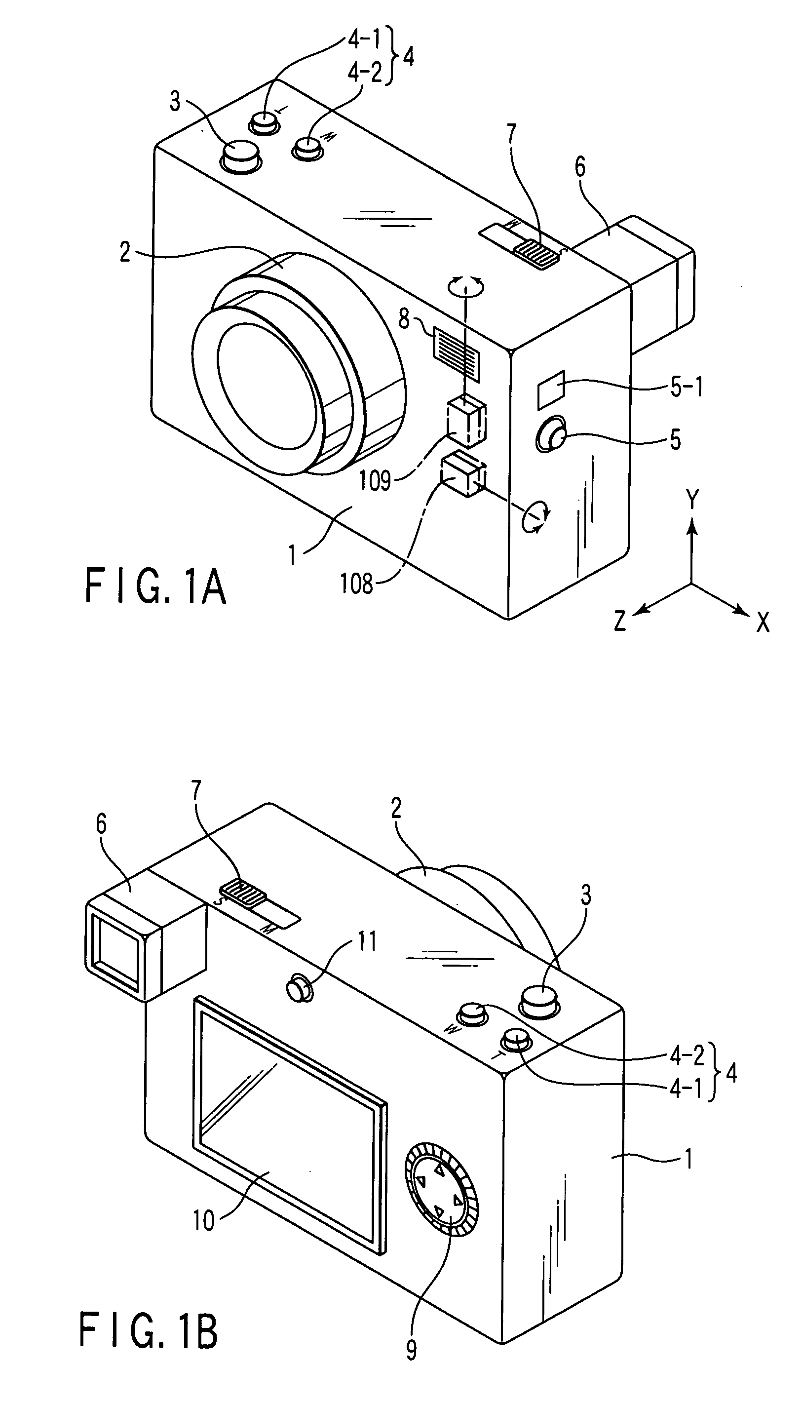
[0070]FIG. 1A is a front surface perspective view of a digital camera which is one example of an image pick-up apparatus according to a first embodiment of the present invention, and FIG. 1B is a back surface perspective view of the digital camera which is one example of the image pick-up apparatus according to the first embodiment of the present invention.
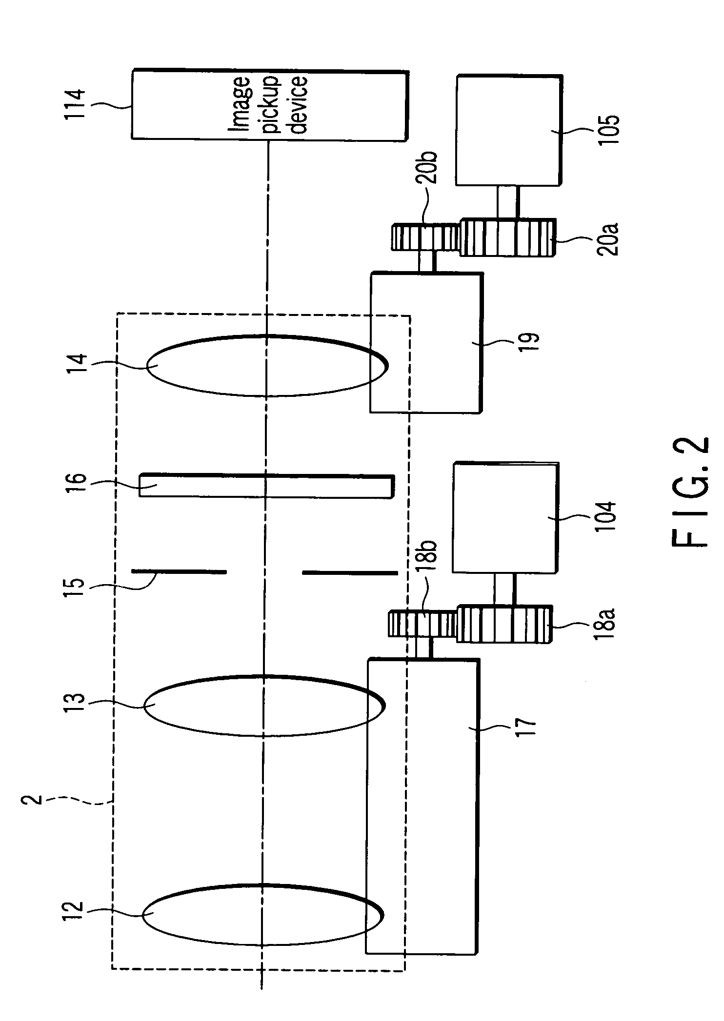
[0071] As seen from FIG. 1A, a lens unit 2 is connected to a front surface of a camera body 1. As seen from FIG. 1B, a finder (view finder) 6 is integrally assembled to a back surface of the camera body 1. The lens unit 2 comprises a plurality of lens for photography, and a driving section. The lens unit 2 will be described later in detail with reference to FIG. 2.
[0072] When a release switch 3 is pressed (turned on), a photographing operation is started. A zoom switch 4 includes a T button 4-1 and a W button 4-2. When the T button is pressed, a magnification of the photographing lens is changed to a telescope side. When the W b...
second embodiment
[0107] Even in a camera provided with a vibration correcting unit in which a restoring operation is performed from image data obtained after a still image is photographed, the vibration correcting unit for performing the above-described type of image restoring operation cannot be applied to through image display for observing a subject in a preparatory stage for the photographing of the still image. Even when the unit is applied, target effects cannot be obtained. To solve the problem, in a second embodiment, vibration correcting is performed which differs with the time of the photographing of the still image and the time of the displaying of the through image as shown in FIGS. 7, 8. That is, the vibration correcting for the moving image (through image) is performed at the time of the displaying of the through image, and the different type of vibration correcting is performed for the still image at the time of the photographing of the still image. Furthermore, the through image in a...
third embodiment
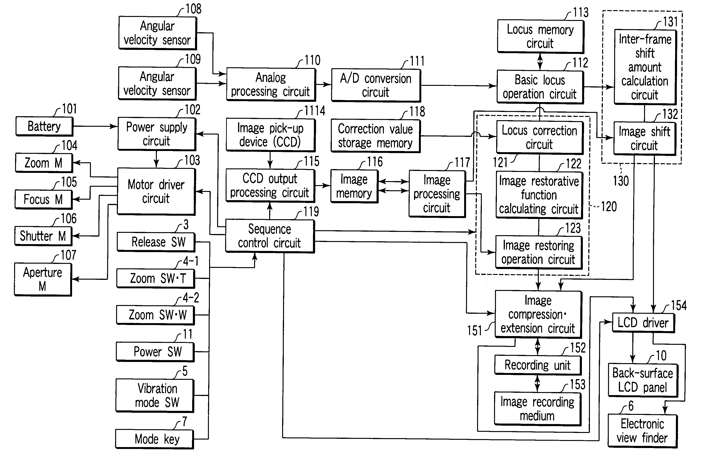
[0110] A third embodiment will be described with reference to FIGS. 9 to 12. In the embodiment, with regard to a picked-up image, after lens distortion correcting is performed, electronic vibration correcting for a still image, and that for a moving image are performed. Here, FIG. 9 is a block diagram of a control circuit of a digital camera. As shown in FIG. 9, the third embodiment is different from the embodiment of FIG. 3 in that a correction value storage memory 118 and a locus correction circuit 121 are omitted, and a distortion correcting value memory 171 (distortion information storage unit, image deterioration information storage unit) and an image distortion correcting circuit 172 are added as constituent elements. It is to be noted that even in the third embodiment, FIGS. 1 to 8 except FIG. 3 are referred to in common to the first and second embodiments. Additionally, the third embodiment is different from the first embodiment in that the picked-up image is additionally co...
PUM
 Abstract
Description
Claims
Application Information
 - R&D Engineer
- R&D Manager
- IP Professional
- Industry Leading Data Capabilities
- Powerful AI technology
- Patent DNA Extraction
Browse by: Latest US Patents, China's latest patents, Technical Efficacy Thesaurus, Application Domain, Technology Topic, Popular Technical Reports.
© 2024 PatSnap. All rights reserved.Legal|Privacy policy|Modern Slavery Act Transparency Statement|Sitemap|About US| Contact US: help@patsnap.com