Apparatus for producing a pharmaceutical product

a technology for producing apparatus and pharmaceutical products, applied in the field of apparatus for manufacturing pharmaceutical and pharmaceuticallike products, can solve the problems of incomplete batch testing, incomplete batch testing, and inability to accurately measure the effect of a single dose, so as to improve the manufacture of pharmaceutical products and eliminate incorrect doses

Inactive Publication Date: 2006-01-26
GLAXO SMITHKLINE LLC
View PDF99 Cites 97 Cited by
  • Summary
  • Abstract
  • Description
  • Claims
  • Application Information

AI Technical Summary

Benefits of technology

[0011] It is an object of the present invention to provide a more efficient apparatus for manufacturing pharmaceutical and pharmaceutical-like product.
[0013] It is yet another object of the present invention to provide such an apparatus that provides real-time feedback and control of the process and product quality.
[0015] It is still another object of the present invention to provide such an apparatus that minimizes or eliminates off-line quality control inspection and facilitates real-time release of the product.
[0017] It is still a further object of the present invention to provide such an apparatus that eliminates an incorrect dose.
[0018] It is yet another further object of the present invention to provide an apparatus that employs Process Analytical Technology to improve the manufacture of pharmaceutical product.

Problems solved by technology

However, these batch-sampling techniques suffer from drawbacks because of their inefficiency and inaccuracy.
If the chosen unacceptable samples do not have the same characteristics as other acceptable product in the batch, then acceptable product may be discarded along with the rejected samples or at least need to undergo more costly testing.
Batch-sampling can be particularly inaccurate where the error or flaw in the process is random, non-repeating or of a non-linear nature.
Such flaws or errors in the manufacturing process may provide for only a fraction of the product of the batch being unacceptable but result in an entire batch being discarded or re-tested, as a result of the use of batch sampling.
Another significant drawback of batch-sampling techniques is where the chosen samples meet the required tolerances, but where a fraction of the batch is actually unacceptable and not representative of the tested sample.
In such a situation, unacceptable product may be provided to the consumer because of the inherent flaw in the quality control method.
An additional drawback in batch-sampling techniques is that the testing is done at the end of the process and provides little, if any, information for corrective action to be taken with regard to the manufacturing process and its various steps.
The batch-sampling technique can provide overall information for sampled product, but does not indicate at which point or which particular step in the process that a flaw is occurring, such as, for example, inadequate dosing or detrimental heating.
Another drawback of batch-sampling technique is that it is done off-line of the manufacturing process, which adds time to the overall manufacturing process, and can also be labor intensive.
The cost in time and labor is increased where more stringent standards are applied to a particular product so the batch-sampling technique utilizes a higher portion of samples for testing.

Method used


Image

  • Apparatus for producing a pharmaceutical product
  • Apparatus for producing a pharmaceutical product
  • Apparatus for producing a pharmaceutical product

Examples


first embodiment

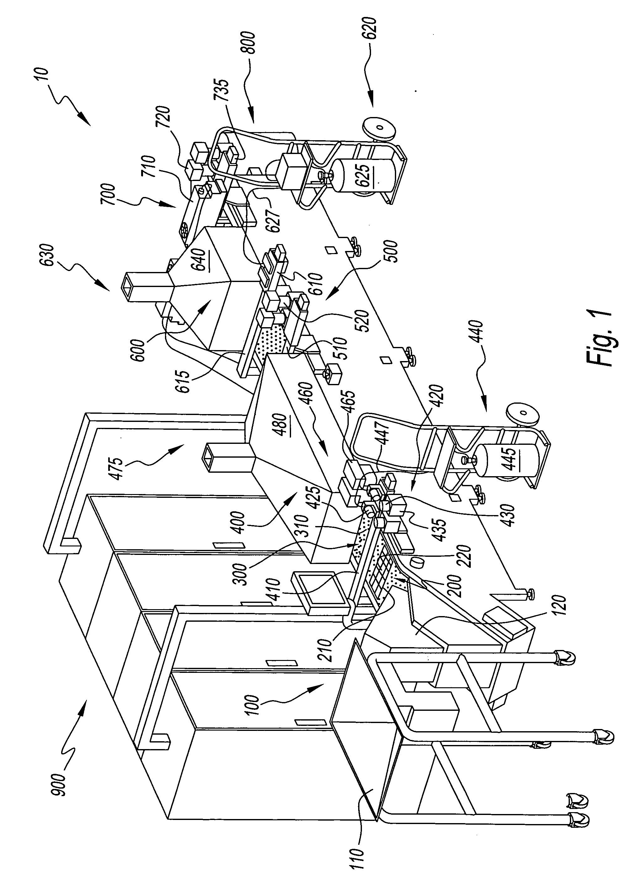
[0216] Referring to FIGS. 11 and 12, the carrier tablet 1000 and the resulting pharmaceutical product 3000, after being processed by machine 10, are shown. The carrier tablet 1000 preferably has a recess or reservoir 1150 disposed centrally along outer surface 1100. Reservoir 1150 provides a basin for the dose droplet 2100 to land after being dispensed to avoid spillage. The reservoir 1150 has a volume that is sufficient to hold the liquid dose 2000. Depending on the viscosity of the liquid dose 2000, the volume of the reservoir 1150 may be less than the volume of the liquid dose (where the viscosity allows the liquid dose to curve above the open end of the reservoir) or may be equal or slightly more than the dose volume.

[0217] The reservoir 1150 is preferably smoothly concave to minimize or avoid splashing. However, the present invention contemplates the use of other shapes, sizes and positions for reservoir 1150 to facilitate the dose droplet being added to the carrier tablet 1000...

second embodiment

[0220] Referring to FIGS. 13 and 14, a carrier tablet 9000 and the resulting pharmaceutical product 3010, after being processed by machine 10, are shown. The carrier tablet 9000 preferably has a recess or reservoir 9150 disposed centrally along outer surface 9100. Reservoir 9150 provides a basin for the dose droplet 2100 to land after being dispensed to avoid spillage. Additionally, a second reservoir (not shown) can be used to surround reservoir 9150, which provides a basin for the coating to land after being dispensed to avoid spillage and to provide a more uniform appearance.

[0221] It should be understood that alternative sizes and shapes for carrier tablets 1000 and 9000 can also be used. For example, but not limited to, machines 10, 20 and 20′ could dispense liquid dose 2000 into gelatin, Hydroxy Propyl Methyl Cellulose (HPMC) or injection molded polymer capsule shells, or any combinations thereof, where the shell is used to hold the dose.

[0222] It should further be understood...


PUM

PropertyMeasurementUnit
volumesaaaaaaaaaa
wavelengthaaaaaaaaaa

Abstract

An apparatus is provided for producing pharmaceutical and pharmaceutical-like product. The apparatus provides real-time monitoring of the pharmaceutical product and can provide real-time control. The apparatus monitors the dosage both before and after it has been added to a carrier substrate. The apparatus can provide monitoring of each pharmaceutical product that is processed.

Description

RELATED APPLICATIONS [0001] This application is related to, and claims priority in, co-pending U.S. Provisional Application Ser. No. 60 / 621,992, filed Oct. 25, 2004, the disclosure of which is incorporated herein by reference. This application is also related to, and claims priority in, co-pending U.S. Provisional Application Ser. No. 60 / 578,245, filed Jun. 9, 2004, the disclosure of which is incorporated herein by reference.BACKGROUND OF THE INVENTION [0002] 1. Field of the Invention [0003] The present invention relates to the manufacture of pharmaceutical and pharmaceutical-like product. More particularly, the present invention relates to an apparatus for manufacturing pharmaceutical and pharmaceutical-like product. [0004] 2. Description of Related Art [0005] Contemporary quality control methods for pharmaceutical and pharmaceutical-like product involve the use of batch sampling techniques. The batch-sampling techniques test samples from batches of the product, such as through the...

Claims


Application Information

Patent Timeline
Patent Type & Authority Applications(United States)
IPC IPC(8): G01J3/00A61J3/00B67B7/00
CPCA61J3/00Y10T436/2575B41P2200/00B41P2200/31G01N21/359G01N21/64G01N21/93G01N21/9508G01N2021/6417A61J3/005A61J3/007G01N21/3563Y10T436/12Y10T436/11Y10T436/113332A61J3/10C23C16/52B05C11/10
Inventor CLARKE, ALLAN J.DOUGHTY, DAVID GEORGEFIESSER, FREDERICK H.WAGNER, DAVID S.
Owner GLAXO SMITHKLINE LLC
Why Eureka
Try Eureka