
Appliance for use with apparatus providing therapy

a technology for providing therapy and apparatus, applied in the field of applications, can solve problems such as inability to closely control the dose rate, inconsistent treatment, tissue receiving too much radiation, injury,

Inactive Publication Date: 2006-01-26
MINNESOTA MEDICAL PHYSICS LLC
View PDF4 Cites 2 Cited by
  • Summary
  • Abstract
  • Description
  • Claims
  • Application Information

AI Technical Summary

Benefits of technology

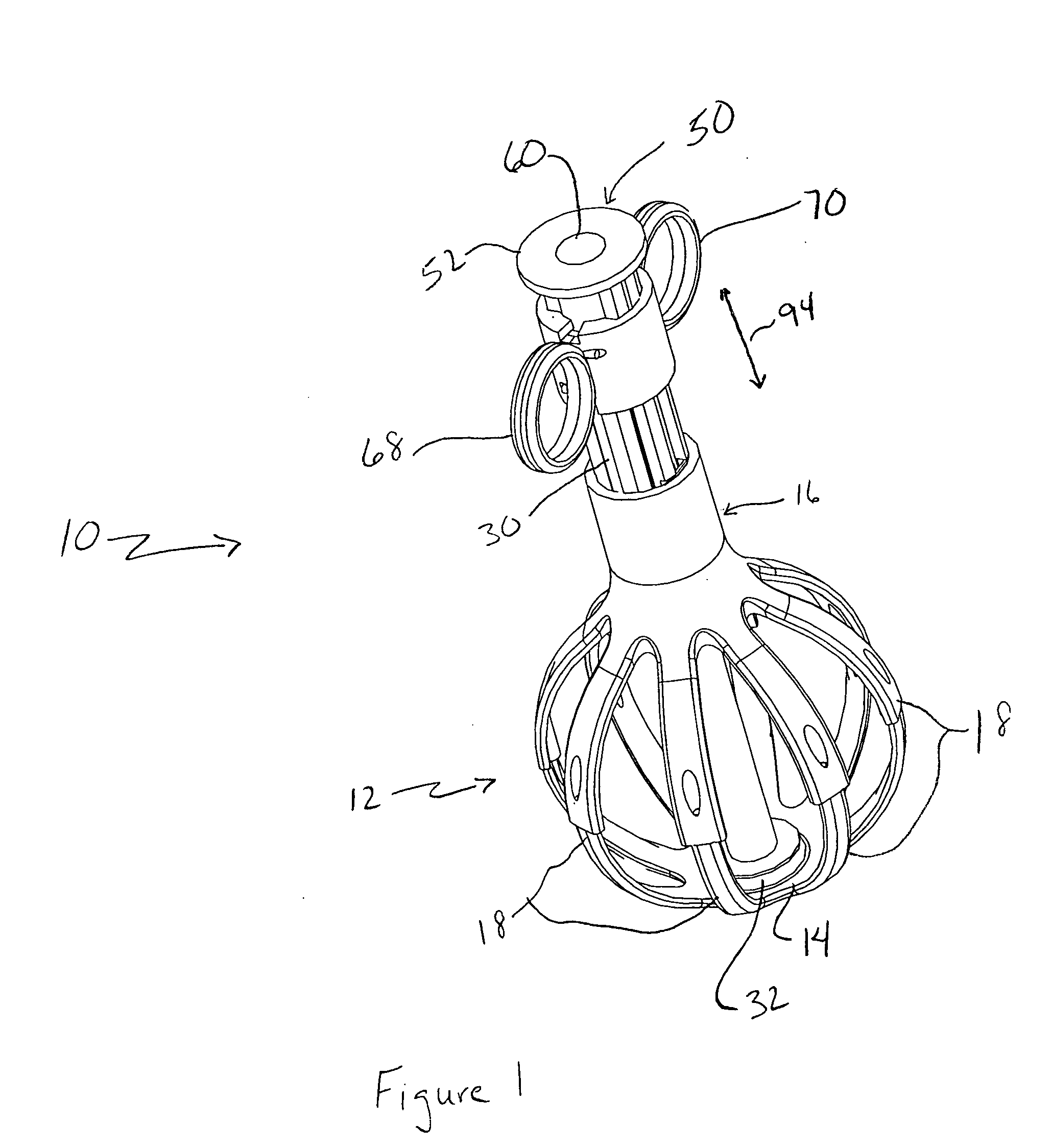
[0011] In one embodiment of the invention, the bulb may include a collar extension having a central passage configured to receive the bulb member. A latch useful with such an embodiment may provide a knob that is attached to the bulb, in particular the bulb collar, that is inwardly extending, and that is received by one of a plurality of appropriately configured holes in the bulb member. To engage and disengage the knob from the holes, the collar extension may include a substantially saw-tooth shaped ramp surface that engages the inner surface of the collar. Relative motion of the collar and the collar extension will cause the collar to move inwardly and outwardly with respect to the collar extension and thus the bulb member, thereby causing the knob to engage and disengage the holes.

Problems solved by technology

An undesirable feature of known field x-ray emitter devices is the inability to closely control the dose rate.
Because of the inconsistency in the current and thus the x-ray beam flux, the dose applied during any particular therapy session may not be well known, which leads to inconsistent treatment and results.
Due to the perhaps irregular configuration of the cancerous tissue and the removed margin tissue, providing a controlled dose of therapeutic radiation to the remaining, surrounding tissue can be problematic, resulting is some tissue receiving too much radiation and being injured and some tissue perhaps not receiving enough to kill any remaining cancer cells.

Method used


Image

  • Appliance for use with apparatus providing therapy
  • Appliance for use with apparatus providing therapy
  • Appliance for use with apparatus providing therapy

Examples


Embodiment Construction

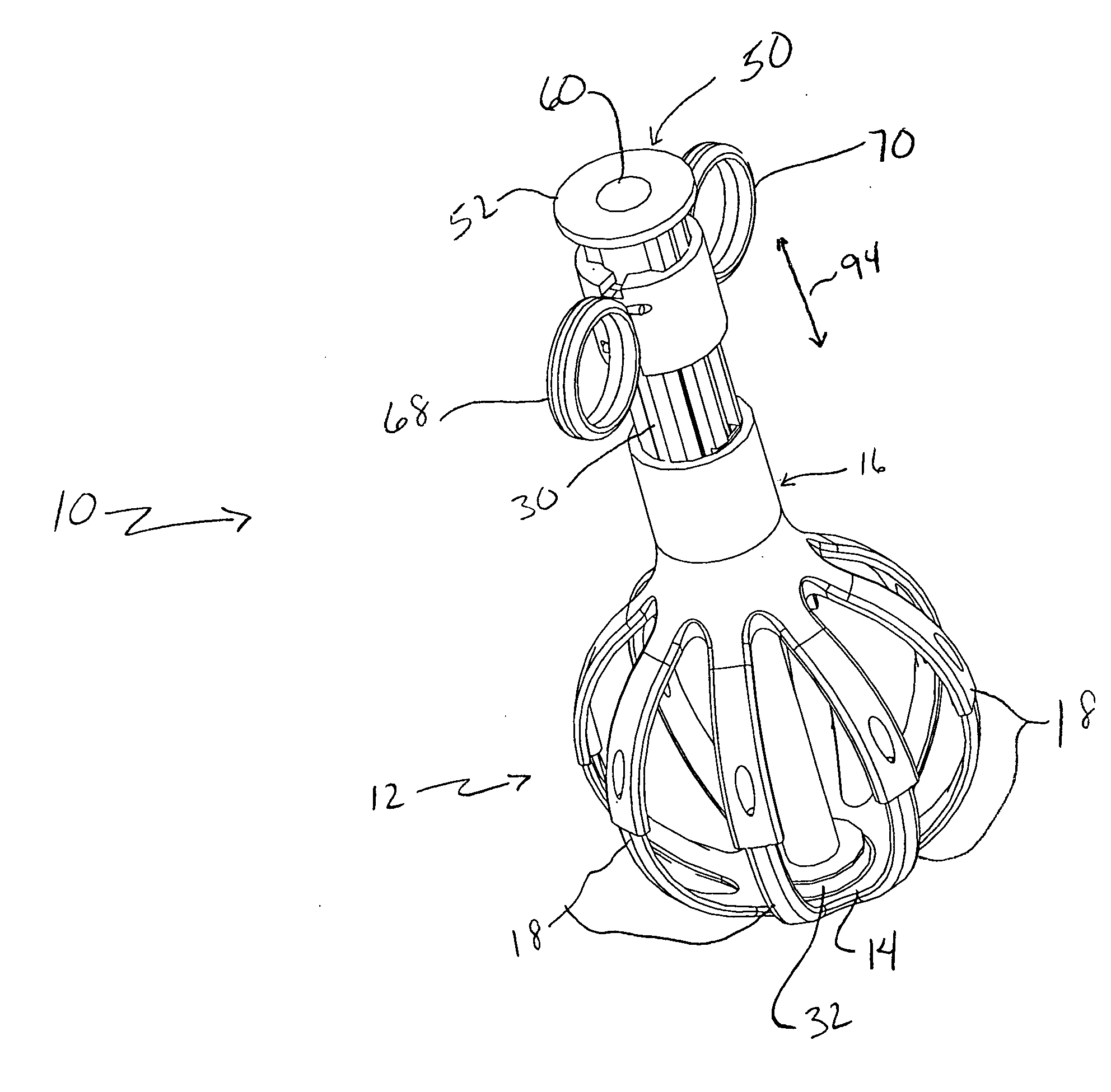
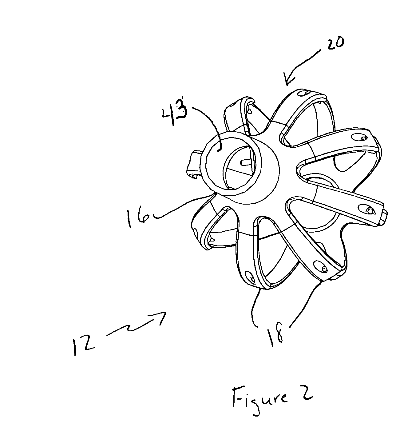
[0039] Referring now to FIGS. 1-10, an embodiment of the present invention will now be described. Thus, as shown in the Figures, an appliance 10 may include an expandable / contractible bulb 12 including a bulb base 14 and a collar 16. Bulb 12 may include a plurality of spokes 18 extending between the bulb base 14 and collar 16. The particular embodiment shown in FIGS. 1-10 includes 8 such spokes, though other numbers of spokes may be used as desired and appropriate for the tissue in which the appliance 10 may be used.

[0040] The bulb 12 may be manufactured as a single integral item, or it may be manufactured in parts and assembled. For example, as best seen in FIGS. 3 and 4, the bulb 12 may comprise a top bulb half 20 including collar 16 and a bottom bulb half 22. Following manufacture the two halves 20 and 22 may be attached to each other in any known manner appropriate for its intended use. For example, in the embodiment shown in the Figures, each partial spoke 18 in the bottom bul...


PUM


Abstract

An appliance for use in delivering x-ray radiation therapy internally at desired locations in a body is disclosed. The appliance may be inserted into the tissue to receive radiation and expanded to a desired shape, thereby providing a predetermined configuration to the tissue surrounding the appliance. The appliance can be configured to provide a spherical shape, for example, or an elliptical shape if desired.

Description

BACKGROUND OF THE INVENTION [0001] The present application claims priority from U.S. patent application Ser. No. 10 / 392,167 (Published Application No. 20030179854), entitled “X-Ray Apparatus With Field Emission Current Stabilization And Method Of Providing X-Ray Radiation Therapy” and filed on Mar. 19, 2003 and U.S. patent application Ser. No. 10 / 938,971 (Published Application No. 20050038488), also entitled “X-Ray Apparatus With Field Emission Current Stabilization And Method Of Providing X-Ray Radiation Therapy” and filed on Sep. 10, 2004.[0002] The present invention relates generally to an appliance useful in aiding apparatus and methods providing x-ray radiation therapy and specifically to such apparatus and methods for providing x-ray radiation therapy with real-time stabilization of the operating current, and thus the dosage rate. Without limitation to the foregoing referenced patent applications, those applications describe apparatus and method providing x-ray radiation thera...

Claims


Application Information

Patent Timeline
Patent Type & Authority Applications(United States)
IPC IPC(8): A61B1/00A61N5/10H01J35/06H01J35/32
CPCA61B1/32A61N5/1001H01J2235/164H01J35/32H01J2235/064H01J35/065
Inventor CHORNENKY, VICTOR I.JAAFAR, ALI
Owner MINNESOTA MEDICAL PHYSICS LLC
Learn More