
Pull-cord and pulley lacing system

Inactive Publication Date: 2006-02-02
YOUNG TREVOR ALAN
View PDF6 Cites 32 Cited by
  • Summary
  • Abstract
  • Description
  • Claims
  • Application Information

AI Technical Summary

Benefits of technology

[0006] This invention consists of a series of pulleys, attached to opposing sides of an area to be tightened in two rows, with an attachment point for one end of a lace at the end of one of the rows of pulleys (pulleys are interchangeable with extremely low friction holes, but pulleys are preferred and are part of the preferred embodiment of the invention). At the other end of one of the rows of pulleys is a mechanism which pulls one end of the lace, shortening it, thereby pulling the rows of pulleys toward each other. The mechanism consists of a self-

Problems solved by technology

The main disadvantages of such a system are: the crossing portions of the lace must be tightened individually to affect the desired level of tightness at the area adjascent to each hole in the lacing series; it is frequent that a laced object will loosen with use and need to be untied, retightened and retied; undoing the object's laces may be difficult after extended or intense usage; and some objects, such as boxing gloves, require the objects be held into a certain position while pulling and tying two lace ends, which makes it hard to secure such object if only two hands are available.

Method used


Image

  • Pull-cord and pulley lacing system
  • Pull-cord and pulley lacing system
  • Pull-cord and pulley lacing system

Examples


Embodiment Construction

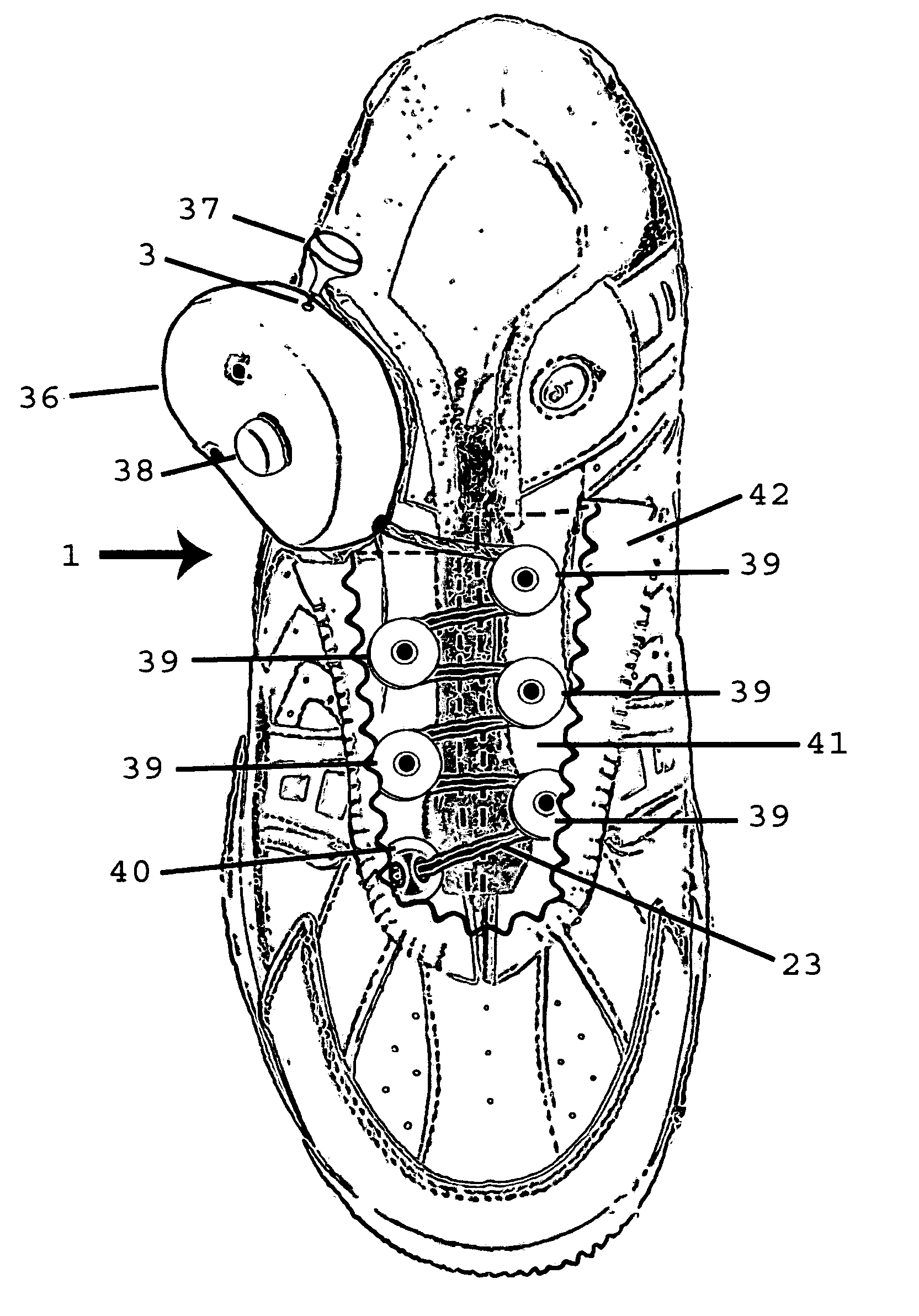
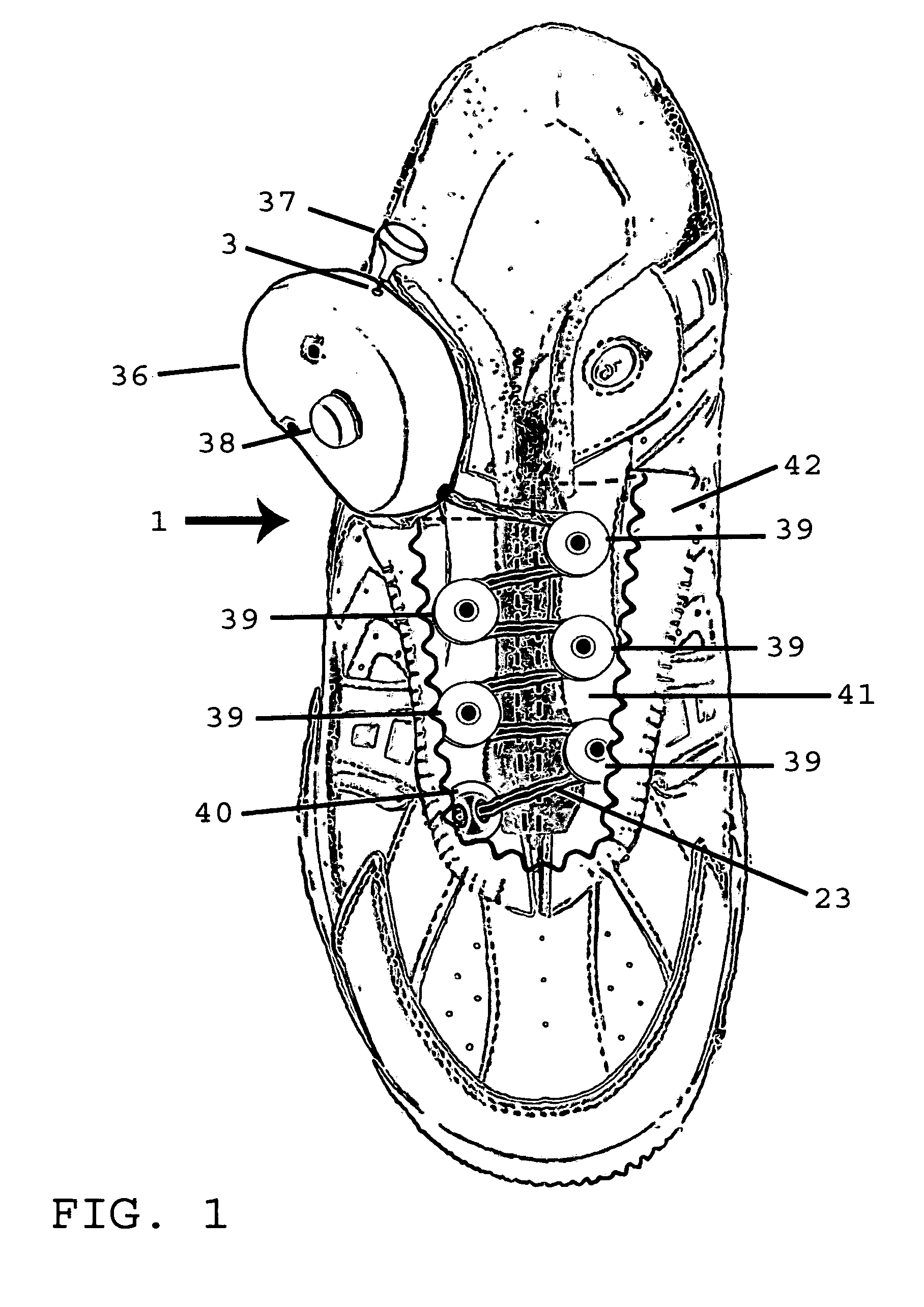
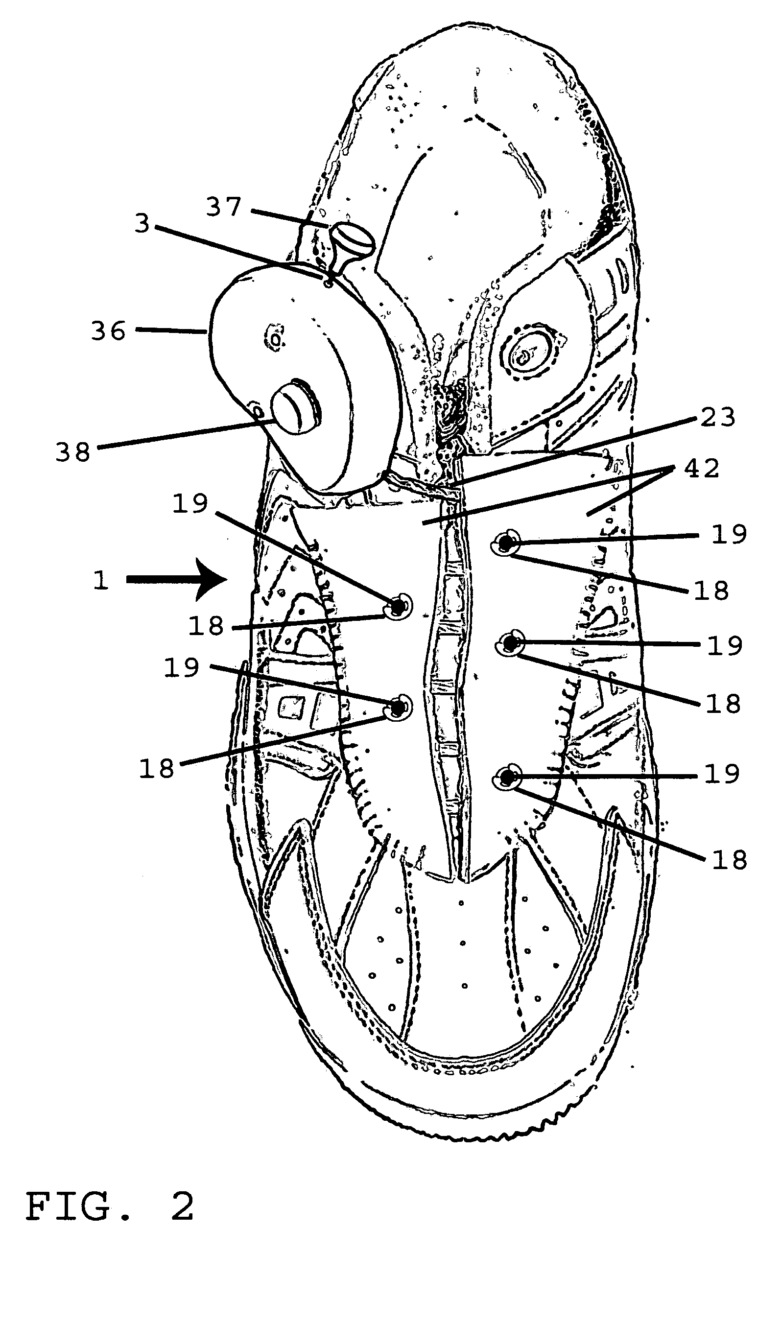
[0046] Referring to FIG. 1, there is disclosed one embodiment of a pull-cord actuated pulley lacing system as used on footwear to tighten it to the user's foot (from herein, it should be understood that the shoe helps illustrate the application of the invention for the purpose of this patent application, and the shoe represents any item to which the invention could be applied). When the pull-cord 3 is pulled, the drawing mechanism 36 pulls the lace 23, shortening the lace length between the drawing mechanism and the attachment point 40, in turn causing the pulleys 39 to draw closer to each other (the lace is threaded around the outer sides of the circumference of the pulleys). In the current embodiment the pulleys 39 are attached to the upper of the shoe by way of axle pins 19, the ends of which are attached to the main upper 41 (below the pulleys) and secondary upper 42 of the shoe (clips 18 hold the pulley on the shoe), allowing the pulleys 39 to turn on a plane generally parallel...


PUM


Abstract

A convenient lacing system including a drawing mechanism, pulleys or some other form of low friction lace paths, an attachment point, and a lace. The lace terminates at the attachment point, and follows a path around the outside hemispheres of the pulleys (or through the lace paths), criss-crossing between the two rows of pulleys without the lace overlapping. The pulleys are aligned generally in two rows on either side of an area to be drawn together. A drawing mechanism is attached at the non-terminating end of the path of the lace, and through use of a pull-cord draws in the lace and tightens the item to which the system is attached by drawing the pulleys (lace paths) closer together. The use of pulleys allows the system to distribute tension evenly along the path of the lace, and aids in the convenience of tightening.

Description

CROSS REFERENCE TO RELATED APPLICATIONS [0001] Provisional Application No. 60 / 591,536 STATEMENT REGARDING FEDERALLY SPONSORED RESEARCH OR DEVELOPMENT [0002] Not Applicable REFERENCES TO A MICROFICHE APPENDIX [0003] Not Applicable BACKGROUND OF THE INVENTION [0004] This invention relates to a convenient lace tightening system for any thing that can be secured using laces (i.e. shoes, boxing gloves, etc.). [0005] The most common way to secure shoes and other laced objects is using a cord which is run in a criss-cross fashion through a series of holes on either side of an area designed to shorten the distance between the adjascent areas, having the ends of the lace exit two parallel holes at one end of the area. These ends are pulled and tied together in some fashion to secure the tightened lace, which in turn secures the item being laced to a desired level of tightness. The main disadvantages of such a system are: the crossing portions of the lace must be tightened individually to aff...

Claims


Application Information

Patent Timeline
IPC IPC(8): A43C7/00
CPCA43C7/00Y10T24/3711A43C11/165
Inventor YOUNG, TREVOR ALAN
Owner YOUNG TREVOR ALAN
Learn More