
Clamp device for securement of scaffolding to large-girth structures

a technology for scaffolding and large girths, applied in the field of scaffolding, can solve the problems of high cost, high risk, and high time-consuming and expensive, and achieve the effects of high safety, easy installation and removal, and large girth

Inactive Publication Date: 2006-02-02
BRAND SERVICES
View PDF5 Cites 1 Cited by
  • Summary
  • Abstract
  • Description
  • Claims
  • Application Information

AI Technical Summary

Benefits of technology

"The invention is a clamp that can safely and easily secure scaffolding or other access apparatus to large-girth structures, such as pipes or buildings. The clamp can be used for various purposes, such as securing walkways or ladders, and can be installed on a wide range of geometries and orientations. The clamp has a linearly elongated rigid support base that is positioned perpendicular to the girth of the structure and carries attachments for the scaffolding or access apparatus. The clamp also has length-adjustable securement members that can be tightened to securely grip the girth of the structure. The securement members are pivotally carried by the base, allowing them to swing and come into tangency with the girth during tightening adjustment. The clamp provides a reliable and safe attachment for workers to use."

Problems solved by technology

These structural members may be vertical, horizontal, sloping, oblique, or otherwise variably oriented, providing an extreme challenge for the typically temporary securement of the scaffolding or walkways on or around them.
This is, to say the least, very time consuming and expensive.
Risk to workers is involved in such operations.
Safety is a critically important issue in the matter of using scaffolding and access structures on immense LDPs of the type used in oil rigs, where workers may find themselves 200 feet or even 300 feet above sea level or other surfaces.

Method used


Image

  • Clamp device for securement of scaffolding to large-girth structures
  • Clamp device for securement of scaffolding to large-girth structures
  • Clamp device for securement of scaffolding to large-girth structures

Examples


Embodiment Construction

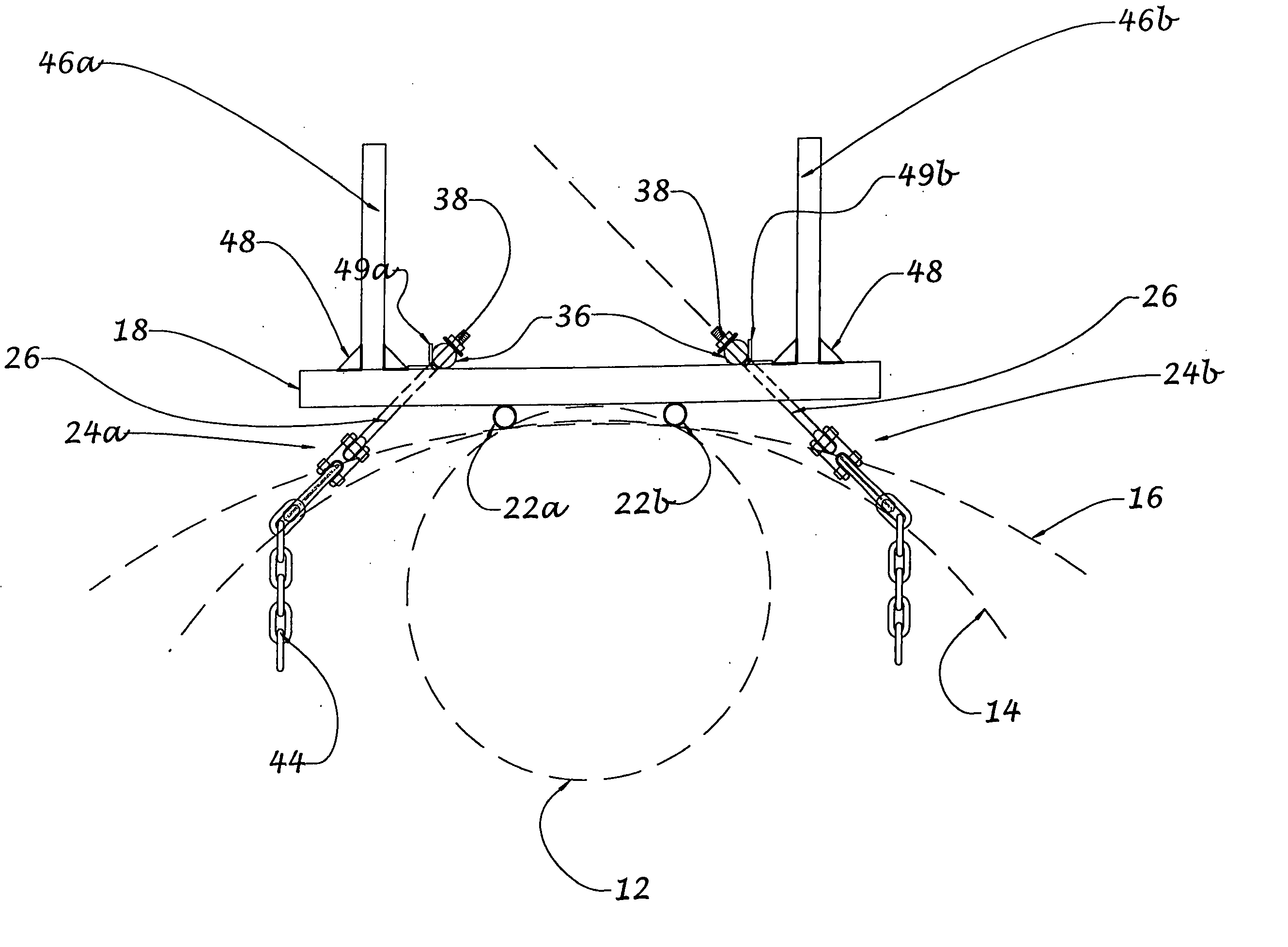
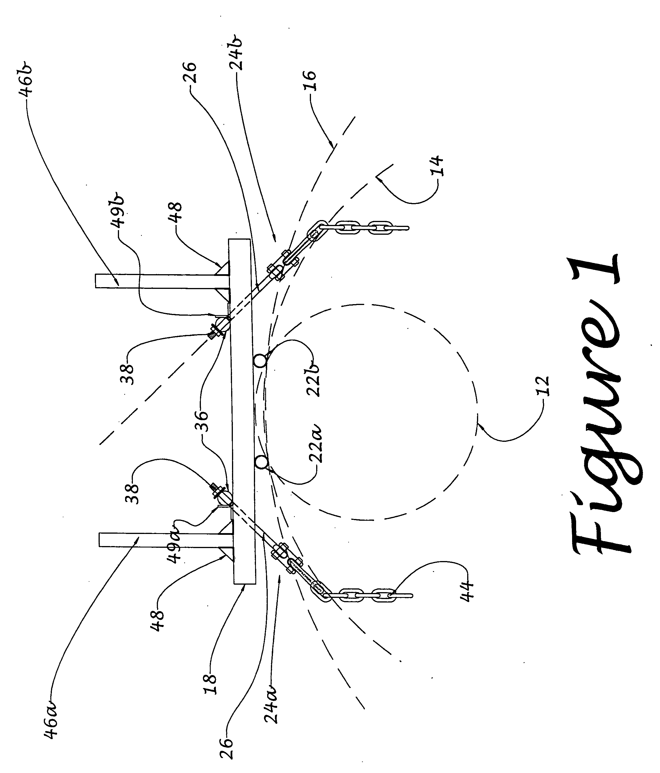
[0025] Referring now to the drawings, particularly the FIG. 1, the new clamp device is designated generally 10. It is here shown as it may be attached to one of several large-girth structures (LDPs). For example, a 30-in. pipe (where the dimension refers to the diameter) is designated at 12, a 7 ft. diameter pipe is 14 and a 12 ft. diameter pipe is at 16. Clamp 10 can be used with any of such large-girth structures for temporary clamping attachment of scaffolding apparatus or other access apparatus (such as catwalks, access ladders, and various possible devices and structures) to any one of possible such LDPs, where the girth could vary over substantially great range such as from a few feet to more than 40 feet, if not greater, and where the orientation of such a structure could also vary, as for example, being vertical, horizontal or oblique, or where the diameter may vary from one end to the other as in a tapered LDP. Therefore, it will be understood that the variety of large-girt...


PUM


Abstract

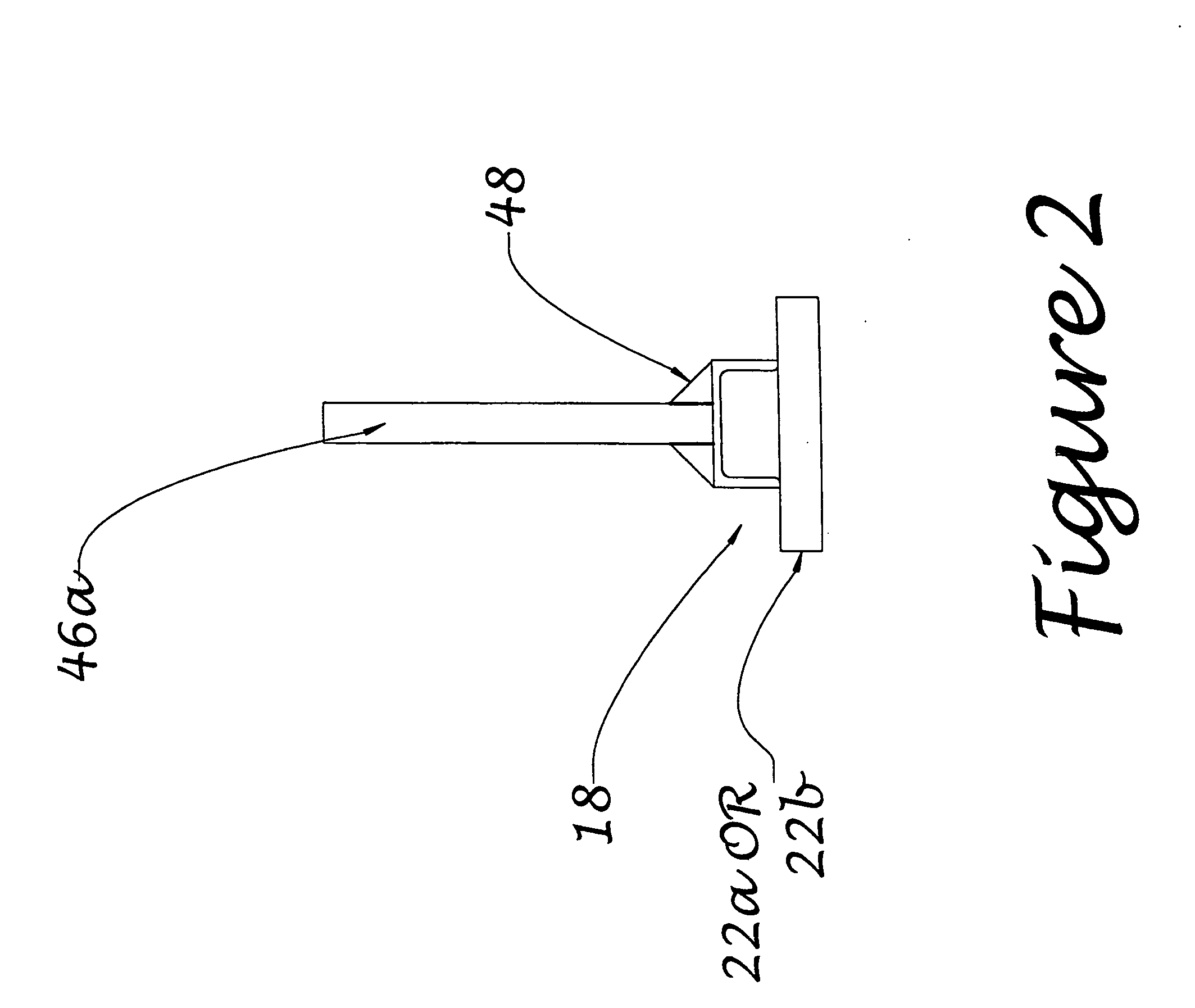
Clamp device (10) for attaching scaffolding or the like apparatus to a large-girth structure (LDP). An elongated base (18) is positioned transversely across the girth. It carries stand-offs (22a, 22b) for spacing the base from the girth. Attachments (46a, 46b) for the scaffolding are at opposite ends of the base. Length-adjustable securement members (24a, 24b) are carried near opposite ends of the base. A flexible elongated girth-encircling member (44), such as a high-strength chain, is extended around the girth, with length adequate for connection to the second securement members which are selectively adjustable in length from the base to cinch the girth-encircling member into tensile condition securely gripping to the girth by tightening adjustment. These adjustable members swing relative to the base so that during their tightening, portions of the length of the girth-encircling member become tangent to points on the girth.

Description

CROSS-REFERENCE TO RELATED APPLICATION [0001] This application claims the priority of U.S. provisional patent application Ser. No. 60 / 592,576, filed Jul. 30, 2004, entitled CLAMP DEVICE FOR SECUREMENT OF SCAFFOLDING TO LARGE-GIRTH STRUCTURES.BACKGROUND OF THE INVENTION [0002] The invention relates to scaffolding and related structures and, more particularly, to apparatus for securement of scaffolding, walkways and other scaffolding and other access components or apparatus to large-girth structures such as large diameter pipes, columns and other structural components used for example in oil rigs and platforms. [0003] Off shore oil rigs and platforms are of immense size and height, being typically enormous structures of steel or concrete members standing on the sea floor, or in some cases, floating rigs or structures held in place by cables attached to a sea floor or otherwise anchored. These structures often include steel pipes or tubes having diameters up to several feet in diameter...

Claims


Application Information

Patent Timeline
Patent Type & Authority Applications(United States)
IPC IPC(8): E04G3/00
CPCE04G5/04E04G3/24
Inventor WHITE, MICHAEL A.TODD, ERIC D.THERIOT, DEREK JEANMENDEZ, ENRIQUE JR.
Owner BRAND SERVICES
Learn More