Bottom drawer type refrigerator having basket lift device
a refrigerator and bottom drawer technology, applied in the field of drawers, can solve problems such as inconvenience for users, and achieve the effect of enhancing users' convenien
- Summary
- Abstract
- Description
- Claims
- Application Information
AI Technical Summary
Benefits of technology
Problems solved by technology
Method used
Image
Examples
first embodiment
[0040]FIG. 5 is a rear perspective view of the basket lift device of the refrigerator in accordance with the present invention, and
[0041]FIG. 6 is a top plan view of the basket lift device of the refrigerator in accordance with the first embodiment of the present invention.
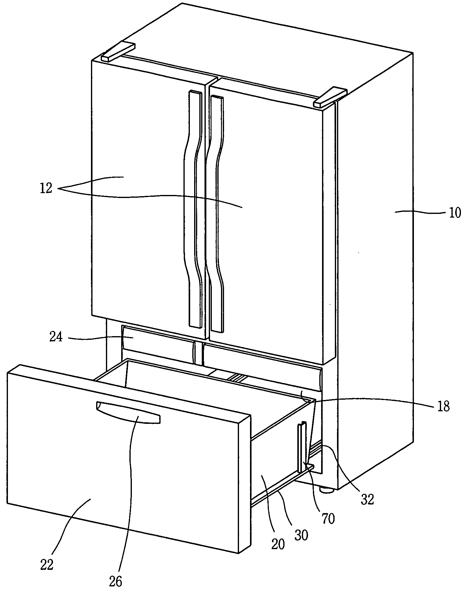
[0042] The lift unit includes a lift frame 36 disposed above the base frame 30, on which the basket 20 is placed, a gas spring 38 installed at the base frame 30 and generating force for lifting the lift frame 36, and a pair of lift rails 40 for guiding the lift frame 36 to be moved linearly up and down.
[0043] The gas spring 38 includes a cylinder 42 charged with high pressure gas, fixed at the base frame 30 and disposed vertically; and an operation rod 44 inserted to be movable up and down in the cylinder 42 and linearly moved by the pressure of the gas charged in the cylinder 42, an upper end of the operation rod 44 being fixed at the lift frame 36.
[0044] A vertical riser portion 46 is formed extending at a ri...
second embodiment
[0061]FIG. 11 is a top plan view of the basket lift device of the refrigerator in accordance with the present invention, and FIG. 12 is an enlarged view of a portion ‘C’ in FIG. 11.
[0062] The basket lift device in accordance with the second embodiment has the same structure as the basket lift device of the first embodiment of the present invention, except for the locking unit for locking the lift frame 36.
[0063] In the second embodiment of the present invention, the locking unit includes buttons 76 mounted at both upper and lower portions of the drawer door 22, an operation rod 78 connected with each button 76 and rotatably disposed inside the drawer door 22 so as to be rotated when the button 76 is pressed, a spring 82 mounted at one side of each operation rod 78 and providing an urging elastic force to the operation rod 78, and a locking detent 80 formed in the guide protrusion 52, in which an end of each the operation rod 78 can be caught.
[0064] When the lift frame 36 is placed...
third embodiment
[0068]FIG. 13 is a top plan view of the basket lift device of the refrigerator in accordance with the present invention, and FIG. 14 is an enlarged view of a portion ‘D’ in FIG. 13.
[0069] A basket lift device in accordance with the third embodiment of the present invention has the same structure except for the locking unit for locking the lift frame.
[0070] In the third embodiment of the present invention, the locking unit includes an actuator 86 mounted at a lower portion of the drawer door 22 or at both the upper and lower portions of the drawer door 22, an operation rod 88 connected with the actuator 86 and linearly moved according to driving of the actuator 86, and a locking detent 90 formed in the side of the guide protrusion 52 of the lift frame 36, in which the operation rod 52 can be insertedly caught.
[0071] The actuator 86 is preferably formed as a solenoid type for linearly and reciprocally moving the operation rod when power is applied thereto.
[0072] A through hole 92 i...
PUM
 Abstract
Description
Claims
Application Information
 - R&D
- Intellectual Property
- Life Sciences
- Materials
- Tech Scout
- Unparalleled Data Quality
- Higher Quality Content
- 60% Fewer Hallucinations
Browse by: Latest US Patents, China's latest patents, Technical Efficacy Thesaurus, Application Domain, Technology Topic, Popular Technical Reports.
© 2025 PatSnap. All rights reserved.Legal|Privacy policy|Modern Slavery Act Transparency Statement|Sitemap|About US| Contact US: help@patsnap.com


