
System and method for image luminance transformation

a technology of luminance and display system, applied in the field of display system, can solve the problems of affecting the image quality of the pilot, affecting the pilot's night vision adaptation, and affecting the effect of image brightness, so as to achieve good contrast and hue, and effective display of images

Inactive Publication Date: 2006-02-02
HONEYWELL INT INC
View PDF3 Cites 39 Cited by
  • Summary
  • Abstract
  • Description
  • Claims
  • Application Information

AI Technical Summary

Benefits of technology

[0010] The image conversion system is particularly applicable to avionics displays where the system must be able to effectively display images over a wide range of ambient light conditions. Specifically, the image conversion system provides the ability to display images, in low ambient light without degrading the pilot's night vision adaptation, while maintaining good contrast and the hues of the original, where those images originally included a large percentage of white or other high-luminance colors.

Problems solved by technology

Without a sufficiently large range of intensities a viewer of the display may be unable to easily read information from the display in high ambient light conditions, low ambient light conditions, or both.
For example, when attempting to display an image that includes a large percentage of white or other light colors, the resulting bright light can degrade the pilot's night vision adaptation.
Attempts to reduce the intensity by dimming the image can cause a significant loss of image quality.
Specifically, uniformly dimming an image can cause a significant loss of contrast in the displayed image, causing elements of similar color and contrast to lose significantly readability.
Furthermore, attempts to limit brightness of one window by dimming the entire display can negatively impact the view ability of other windows on the display.

Method used


Image

  • System and method for image luminance transformation
  • System and method for image luminance transformation
  • System and method for image luminance transformation

Examples


Embodiment Construction

[0019] The present invention provides an image conversion system and method for altering an image to adjust the overall brightness of the image when displayed. The system and method provide the ability to adjust the overall brightness while maintaining good contrast and the hues of the original color to the extent possible. The system is particularly applicable to avionics display systems.

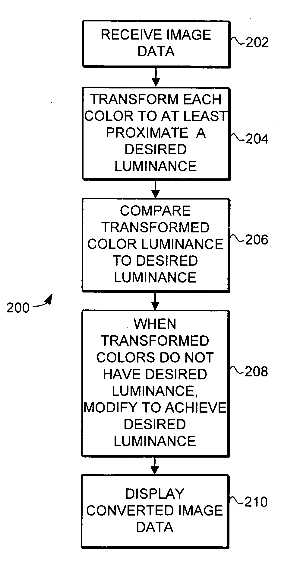
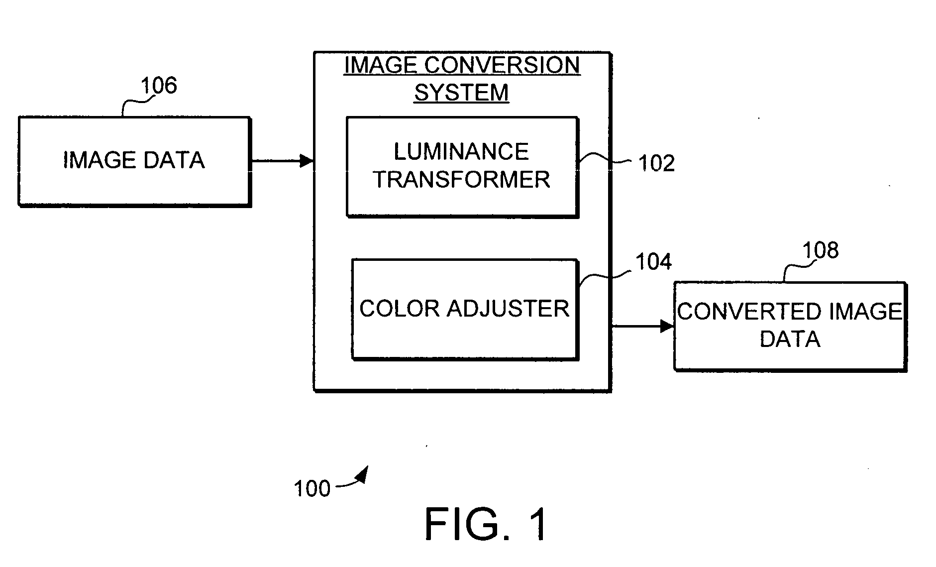
[0020] Turning now to FIG. 1, an image conversion system 100 is illustrated schematically. The image conversion system 100 includes a luminance transformer 102 and a color adjuster 104. The image conversion system 100 receives image data 106 and produces converted image data 108, with the converted image data resulting in a change in the overall brightness of the image when it is displayed. To adjust the overall brightness of the image, the luminance transformer 102 reverses the luminance of each original color in the image. Specifically, the original colors in the image data are each transformed ...


PUM


Abstract

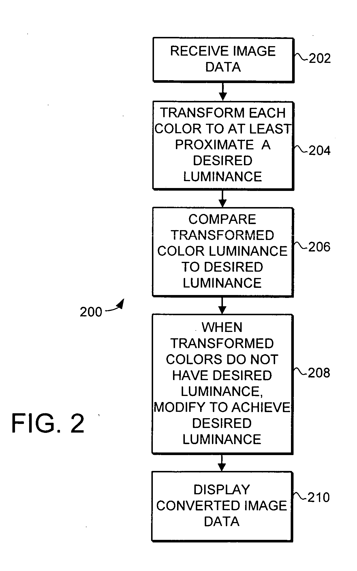
An image conversion system for altering an image to adjust the overall brightness of the image when displayed is provided. The image conversion system includes a luminance transformer and a color adjuster. To adjust the overall brightness of the image, the luminance transformer reverses the luminance of each original color in the image. The new luminance of each transformed color is then compared to the desired luminance for that color. When the transformed colors do not have the desired luminance, the color adjuster modifies the hues of transformed color to achieve the desired luminance. Specifically, the color adjuster modifies the transformed color using a weighted average to achieve the desired luminance while maintaining the hues of the original color to the extent possible. By substituting each original color with a transformed color that is adjusted as needed to reach the desired luminance, the overall brightness of the image is adjusted.

Description

FIELD OF THE INVENTION [0001] This invention generally relates to display systems, and more specifically relates to luminance adjusting for displayed images. BACKGROUND OF THE INVENTION [0002] Various types of optical displays are commonly used in a wide variety of applications. For example, computing devices such as personal computers, workstations, and personal digital assistants (PDA) and communication devices such as mobile phones and radios all use various types of displays. Displays are also commonly used for a variety of purposes on vehicles such as automobiles and aircraft. Optical displays can use a variety of different display mechanisms, such as LCD, CRT, projection and other devices. [0003] One new application in which optical displays are being applied is in aircraft avionics systems. For example, in an aircraft avionics application, a multi-function display can be used to provide a variety of different types of information to the pilot by dividing the display into a pl...

Claims


Application Information

Patent Timeline
IPC IPC(8): G09G5/02
CPCH04N1/6027
Inventor HAMMOND, SCOTT G.
Owner HONEYWELL INT INC
Learn More