
Display panel and method of manufacturing the same

a technology of display panel and display panel, which is applied in the field of display panel, can solve the problems of reducing the transmissive rate of a pixel, cutting portions and protruding, etc., and achieves the effect of increasing the response rate of a liquid crystal display, not reducing the transmissive rate, and increasing the transmissive rate of the unit pixel area

Active Publication Date: 2013-02-28
SAMSUNG DISPLAY CO LTD
View PDF3 Cites 5 Cited by
  • Summary
  • Abstract
  • Description
  • Claims
  • Application Information

AI Technical Summary

Benefits of technology

This patent describes a method for improving the display quality of LCDs by increasing the transmissive rate and viewing angle. This is achieved by forming multiple domains in an alignment layer without creating any patterns that would decrease the transmissive rate. This results in a higher response rate for LCDs and allows for more effective display of images. Additionally, spraying air onto the alignment layer prevents any scratches from occurring during the process. Overall, this method enhances the performance of LCDs and makes them more user-friendly.

Problems solved by technology

However, cutting portions and protrusions decrease a transmissive rate of a pixel.

Method used


Image

  • Display panel and method of manufacturing the same
  • Display panel and method of manufacturing the same
  • Display panel and method of manufacturing the same

Examples


Embodiment Construction

[0046]Hereinafter, exemplary embodiments of the present invention will be described in further detail with reference to the accompanying drawings. However, the present invention may be embodied in various different ways and should not be construed as limited to the exemplary embodiments described herein.

[0047]It will be understood that when an element or layer is referred to as being “on,”“connected to” or “coupled to” another element or layer, it can be directly on, connected or coupled to the other element or layer or intervening elements or layers may be present. Like numbers may refer to like elements throughout the specification and drawings.

[0048]As used herein, the singular forms, “a,”“an” and “the” are intended to include the plural forms as well, unless the context clearly indicates otherwise.

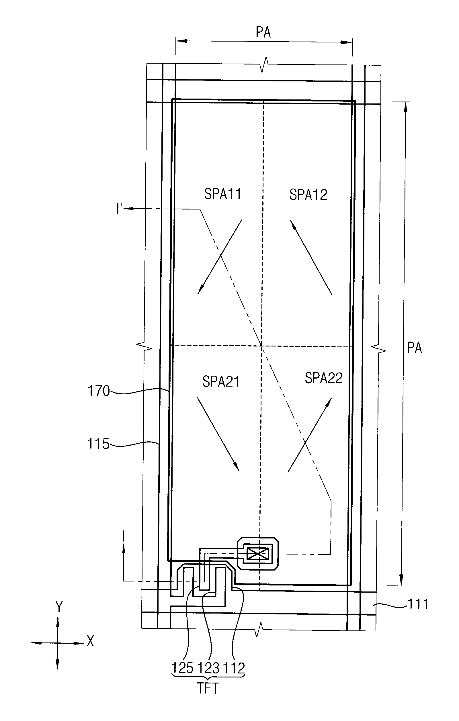
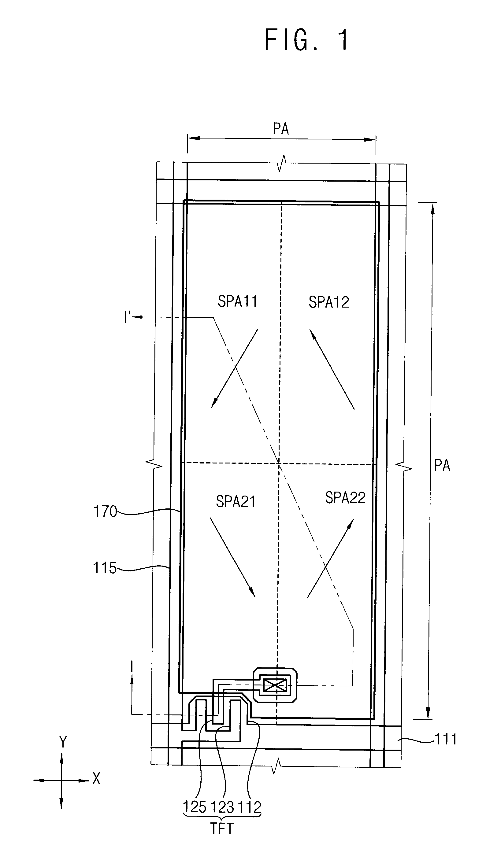
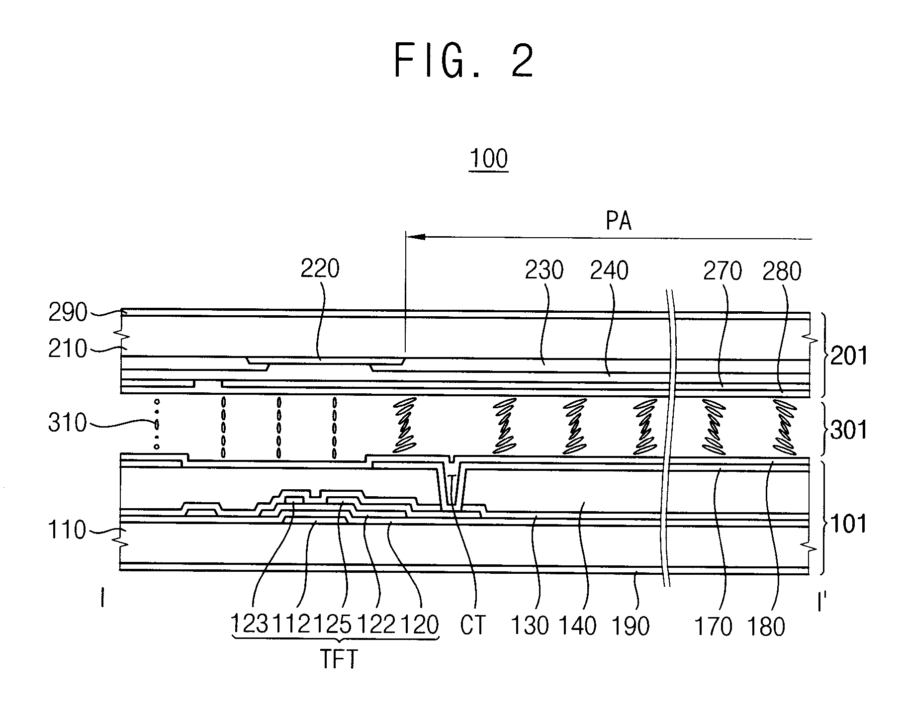
[0049]FIG. 1 is a plan view illustrating a display panel according to an exemplary embodiment of the present invention. FIG. 2 is a cross-sectional view taken along a line I-I′ of FIG....


PUM

PropertyMeasurementUnit
distanceaaaaaaaaaa
distanceaaaaaaaaaa
distanceaaaaaaaaaa

Abstract

Air is sprayed on the first polymer film along a first negative direction in the sub pixel areas of an n-th row of a unit pixel area, and air is sprayed on the first polymer film along a first positive direction in the sub pixel areas of an (n+1)-th row of the unit pixel area to form a first alignment layer. Air is sprayed on the second polymer film along a second negative direction crossing the first negative direction in the sub pixel areas of an n-th column of the unit pixel area, and air is sprayed on the second polymer film along a second positive direction crossing the first positive direction in the sub pixel areas of an (n+1)-th column of the unit pixel area to form a second alignment layer.

Description

CROSS-REFERENCE TO RELATED APPLICATION[0001]This application claims priority to Korean Patent Application No. 2011-84972, filed on Aug. 25, 2011, and all the benefits accruing therefrom under 35 U.S.C. §119, the contents of which in its entirety is herein incorporated by reference.1. TECHNICAL FIELD[0002]Exemplary embodiments of the present invention relate to a display panel and a method of manufacturing the display panel. More particularly, exemplary embodiments of the present invention relate to a display panel having a multi-domain configuration and a method of manufacturing the display panel.2. DISCUSSION OF THE RELATED ART[0003]A liquid crystal display (LCD) apparatus is a type of flat panel display apparatus, and includes two substrates in which field generating electrodes including a pixel electrode and a common electrode are formed, a liquid crystal layer interposed between two substrates and a polarizing plate attached on outer surfaces of the substrates.[0004]An LCD appar...

Claims


Application Information

Patent Timeline
Patent Type & Authority Applications(United States)
IPC IPC(8): G02F1/1343H01L33/08
CPCG02F1/13378G02F1/1303B32B2457/202G02F1/133753G02F2001/133757G02F1/133711G02F1/133757G02F1/1337
Inventor JUNG, JIN-SOOLEE, JUN-WOOJEON, BAEK-KYUNYEOM, JOO-SEOK
Owner SAMSUNG DISPLAY CO LTD
Learn More