Display device and control method for the display device

a display device and control method technology, applied in the field of display devices, can solve the problems of not providing a solution, stereoscopic images cannot be processed by the same method, and have not been examined, so as to achieve the effect of effectively displaying an image, effectively displaying a combined image, and easy arbitrarily adjusting a parallax

Active Publication Date: 2013-12-05
SEIKO EPSON CORP
View PDF5 Cites 4 Cited by
  • Summary
  • Abstract
  • Description
  • Claims
  • Application Information

AI Technical Summary

Benefits of technology

[0018]According to the aspect of the invention, the display device that outputs the image data of the image for the left eye and the image data of the image for the right eye and displays the stereoscopic image on the basis of the input image data can arrange the different image data stored in the memory in appropriate positions in the respective image data of the image for the left eye and image data of the image for the right eye. Consequently, it is possible to combine an image such as an OSD image different from an input image, which is, for example, a stereoscopic image, with the input image using one different image data stored in the memory and display a combined image of the different image and the input image. Since the positions where the different image data is arranged in the respective image data of the image for the left eye and image data of the image for the right eye can be respectively designated, it is possible to display the different image as a plane image and display the different image as a stereoscopic image. It is easy to arbitrarily adjust a parallax when the different image is display as the stereoscopic image. Therefore, it is possible to combine the different image with the input image, which is the stereoscopic image, and effectively display a combined image of the different image and the input image.
[0019]According to the aspects of the invention, it is possible to arrange the different image in appropriate positions in the respective image data of the image for the left eye and image data of the image for the right eye and combine the different image data with the image data. It is possible to effectively display an image such as an OSD image together with an input image.

Problems solved by technology

Concerning a function of superimposing and displaying an image different from an input image on the input image such as the OSD display function, the related art has not provided a solution as to how the OSD image or the like is superimposed and displayed on the input image when the input image is a stereoscopic image.
Therefore, the stereoscopic image cannot be processed by a method same as a method of superimposing plane images each other.
However, it has not been examined, for example, how the OSD image or the like formed by the plane image is superimposed on the stereoscopic image.
However, it has not been examined how processing for superimposing images is combined according to whether the input image is the stereoscopic image or the plane image.

Method used


Image

  • Display device and control method for the display device
  • Display device and control method for the display device
  • Display device and control method for the display device

Examples


first embodiment

[0029]Embodiments of the invention are explained below with reference to the accompanying drawings.

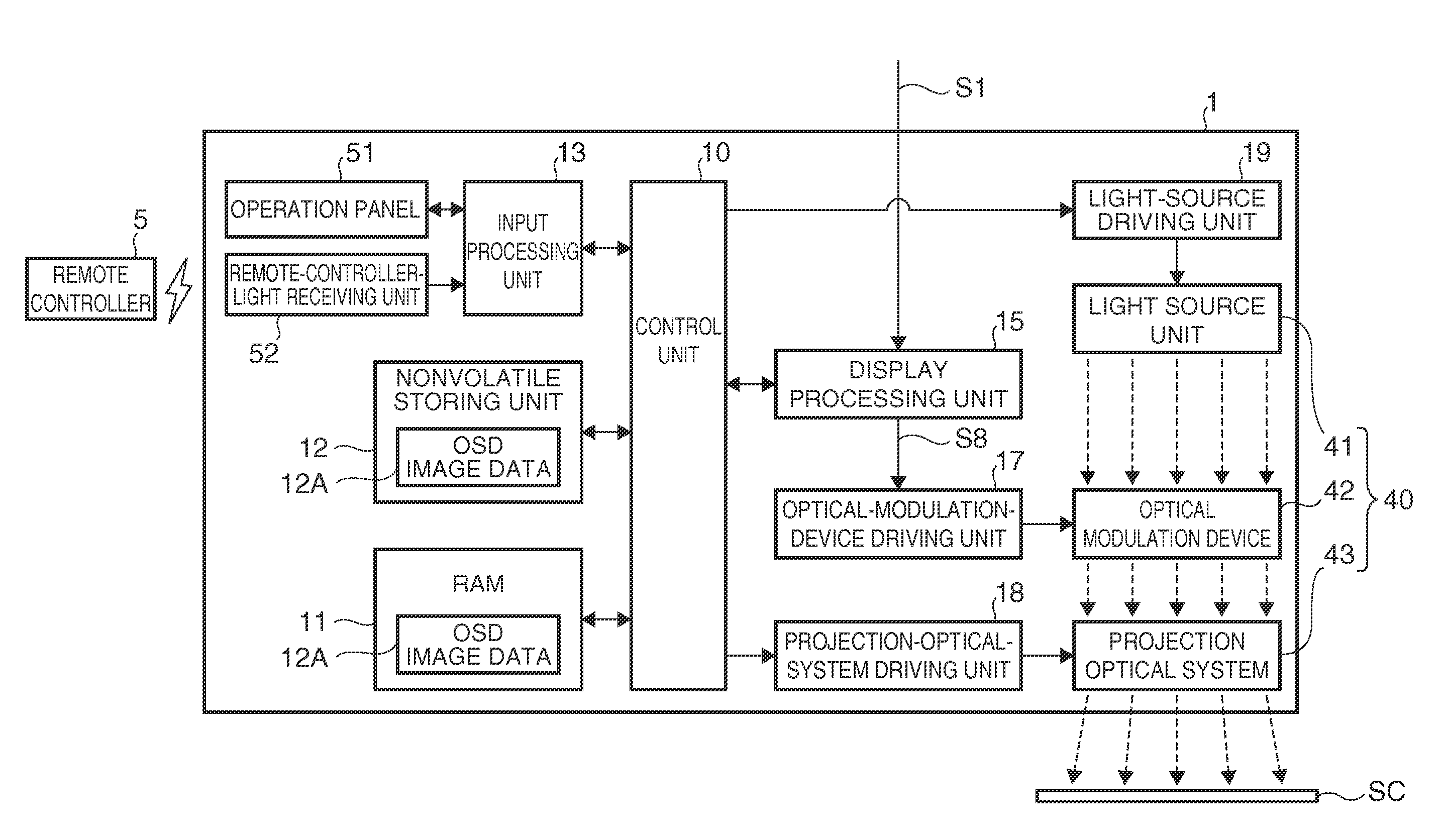
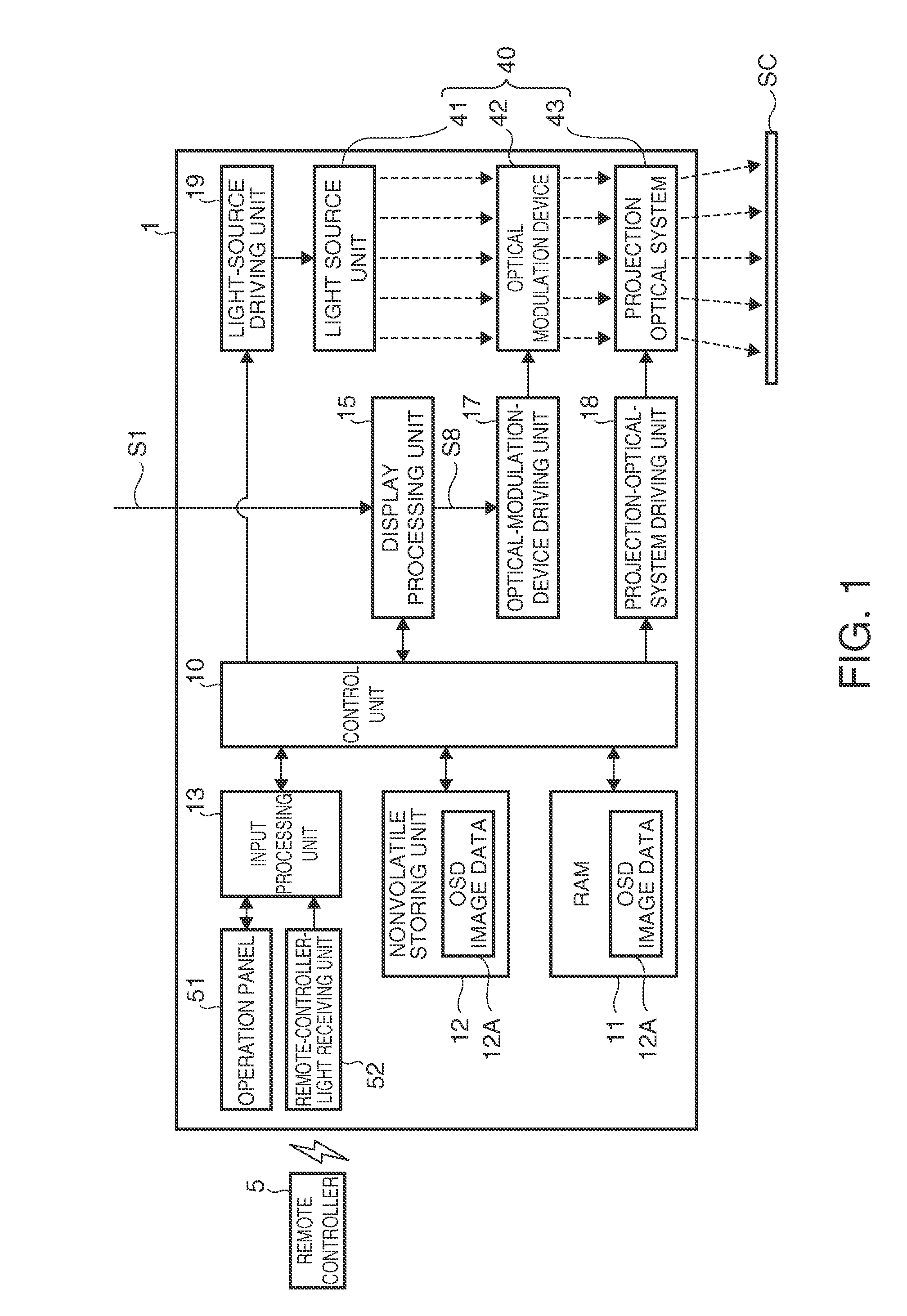
[0030]FIG. 1 is a block diagram showing the overall configuration of a projector 1 functioning as a display device according to a first embodiment. The projector 1 is a device connected to an external image supply device (not shown in the figure) such as a personal computer or various video players and configured to project input image data S1 input from the image supply device on a projection surface such as a screen SC. Examples of the image supply device include video output apparatuses such as a video player, a DVD player, a television tuner apparatus, a set top box of a CATV, and a video game apparatus and a personal computer. In an example explained in this embodiment, digital image data of a moving image is input from the image supply device to a display processing unit 15 as the input image data S1. The digital image data includes, together with image data itself, information c...

second embodiment

[0069]FIG. 6 is a functional block diagram showing the configuration of a display processing unit 15A according to a second embodiment of the invention.

[0070]In an example explained in the second embodiment, the input image data S1 input from an image supply device (not shown in the figure) is side-by-side stereoscopic image data. The configuration of the second embodiment can be easily applied as well when the input image data S1 is a top-and-bottom stereoscopic image.

[0071]The display processing unit 15A shown in FIG. 6 is included in the projector 1 instead of the display processing unit 15 shown in FIG. 1. In the second embodiment, units configured the same as the units in the first embodiment are denoted by the same reference numerals and signs and explanation of the units is omitted.

[0072]The display processing unit 15A includes an image output unit 21A instead of the image output unit 21 (FIG. 2). The image output unit 21A has a function of dividing frames included in the inp...

third embodiment

[0087]FIG. 7 is a functional block diagram showing the configuration of a display processing unit 15B according to a third embodiment of the invention.

[0088]In an example explained in the third embodiment, the input image data 51 input from an image supply device (not shown in the figure) is side-by-side stereoscopic image data. This configuration of the third embodiment can be easily applied as well when the input image data 51 is a top-and-bottom stereoscopic image.

[0089]The display processing unit 15B shown in FIG. 7 is included in the projector 1 instead of the display processing unit 15 shown in FIG. 1. In the third embodiment, units configured the same as the units in the first and second embodiments are denoted by the same reference numerals and signs and explanation of the units is omitted.

[0090]The display processing unit 15B includes an image output unit 21B instead of the image output unit 21 (FIG. 2). Like the image output unit 21A (FIG. 6), the image output unit 21B has...


PUM


Abstract

A projector displays, together with an input image, an OSD image different from the input image. The projector includes an image output unit configured to output image data of an image for the left eye and image data of an image for the right eye, an image processing unit configured to read out a different image data from a RAM, apply, to the image data of the image for the left eye, processing for arranging the different image data in a position for the left eye and combining the different image data with the image data of the image for the left eye, and apply, to the image data of the image for the right eye, processing for arranging the different image data in a position for the right eye and combining the different image data with the image data of the image for the right eye.

Description

BACKGROUND[0001]1. Technical Field[0002]The present invention relates to a display device that displays an image and a control method for the display device.[0003]2. Related Art[0004]As a display device that displays an input image, there has been known a display device having a function of superimposing and displaying an image different from the input image on the image being displayed (JP-A-2008-216460 (Patent Literature 1). This kind of function is called, for example, an OSD display function. A menu screen or the like for setting is displayed as an OSD image together with the input image. As described in Patent Literature 1, in the general OSD display function, the OSD image stored in advance is superimposed on the input image. The device described in Patent Literature 1 combines colors of the OSD image in a pixel unit to thereby display OSD images of various colors.[0005]In recent years, there is known a display device that displays a 3D (stereoscopic) image. This kind of displ...

Claims


Application Information

Patent Timeline
Patent Type & Authority Applications(United States)
IPC IPC(8): H04N13/04H04N13/30
CPCH04N13/04H04N13/156H04N13/183H04N13/30
Inventor SUZUKI, NAOKI
Owner SEIKO EPSON CORP
Why Eureka
Try Eureka