
Information processing apparatus

a technology of information processing and equipment, applied in the field of information processing equipment, can solve the problems of wasteful memory space and inefficient system, and achieve the effect of efficient display of images of different resolutions

Inactive Publication Date: 2007-08-07
NIKON CORP
View PDF21 Cites 2 Cited by
  • Summary
  • Abstract
  • Description
  • Claims
  • Application Information

AI Technical Summary

Benefits of technology

[0014]The present invention was made in consideration of such conditions and is intended to efficiently display images of different resolutions on the same apparatus at the specified resolution.
[0020]Additionally, the information processing apparatus may include a second image input device (e.g., a touch tablet and pen) that inputs a second image, a second filter device (e.g., a low-pass filter) that eliminates the high spatial frequency component of the second image and a second memory device (e.g., the line drawing memory area) that records the second image having the high spatial frequency component eliminated by the second filter device. An interpolation device (e.g., a CPU) may interpolate the second image recorded by the second memory device and a third filter device (e.g., a low-pass filter) may eliminate the high spatial frequency component of the first image output by the first memory device and the second image interpolated by the interpolation device. An output device (e.g., an LCD) may output a third image having superimposed the first image (having the high spatial frequency component eliminated by the third filter device) and the second image (having the high spatial frequency component eliminated by the third filter device).
[0028]The first image input device may input a first image. The first filter device may eliminate the high spatial frequency component of the first image. Additionally, the first memory device may record the first image having the high spatial frequency component eliminated by the first filter device. The second image input device may input a second image and the second filter device may eliminate the high spatial frequency component of the second image. The second memory device may record the second image having the high spatial frequency component eliminated by the second filter device. The interpolation device may interpolate the second image recorded by the second memory device and the third filter device may eliminate the high spatial frequency component of the first image output by the first memory device and the second image interpolated by the interpolation device. The output device may output a third image having superimposed the first image having the high spatial frequency component eliminated by the third filter device and the second image having the high spatial frequency component eliminated by the third filter device.
[0029]The first image input device may input a first image and the first filter device may eliminate the high spatial frequency component of the first image. The first memory device may record the first image having the high spatial frequency component eliminated by the first filter device and the second image input device may input a second image. The second filter device may eliminate the high spatial frequency component of the second image and the second memory device may record the second image having the high spatial frequency component eliminated by the second filter device. The interpolation device may interpolate the second image recorded by the second memory device. Additionally, the output device may output a third image having superimposed the first image recorded by the first memory device and the second image interpolated by the interpolation device.
[0030]Still further, the first image input device may input a first image and the first filter device may eliminate the high spatial frequency component of the first image. The first memory device may record the first image having the high spatial frequency component eliminated by the first filter device. The second image input device may input a second image and the second filter device may eliminate the high spatial frequency component of the second image. The second memory device may record the second image having the high spatial frequency component eliminated by the second filter device. The interpolation device may interpolate the second image recorded by the second memory device. The pixel thinning device may perform pixel thinning on the first image recorded by the first memory device and the output device may output a third image having superimposed the first image having undergone processing by the pixel thinning device and the interpolated second image recorded by the second memory device.

Problems solved by technology

Consequently, there is a problem when inputting line drawings by pen along with inputting images and having the images and line drawings displayed superimposed at the same resolution.
This becomes an inefficient system due to the different resolutions of the images and the line drawings.
For example, when line drawings of characters input by hand are to be superimposed on images read in by electronic cameras and scanners, wasteful memory space may be used to input the line drawings beyond the necessary resolution.

Method used


Image

  • Information processing apparatus
  • Information processing apparatus
  • Information processing apparatus

Examples


Embodiment Construction

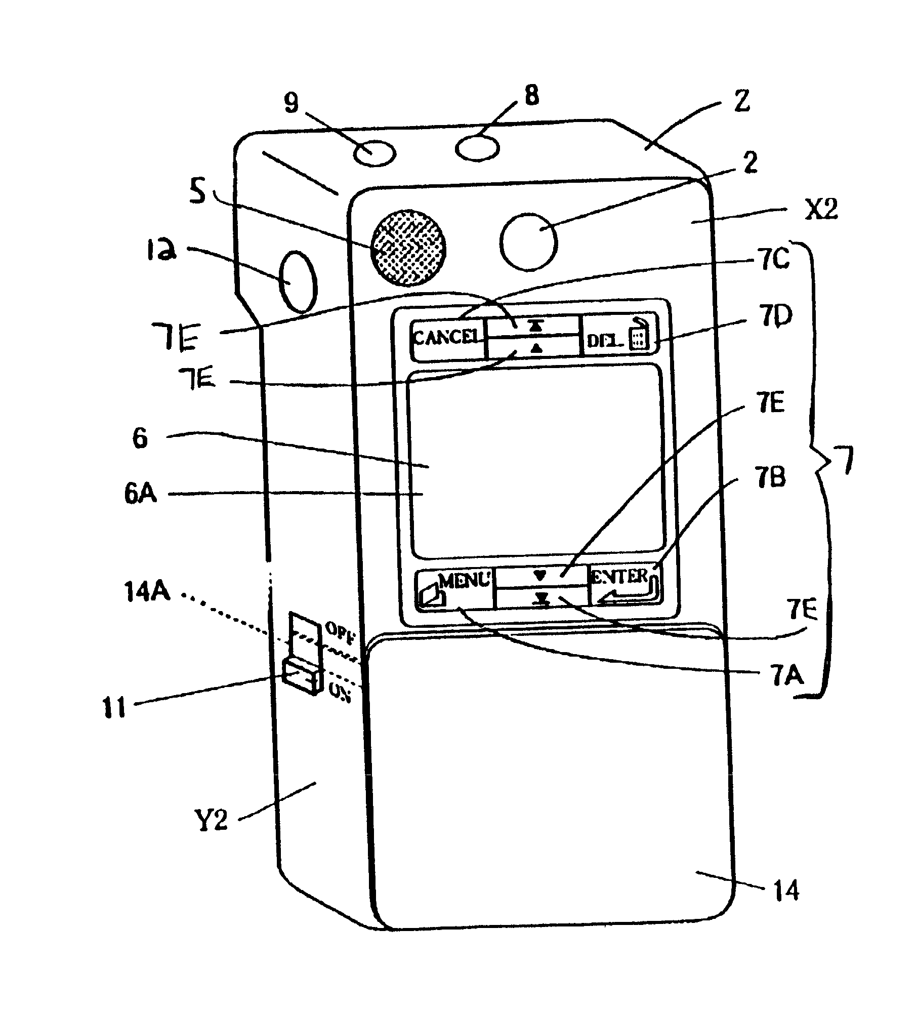
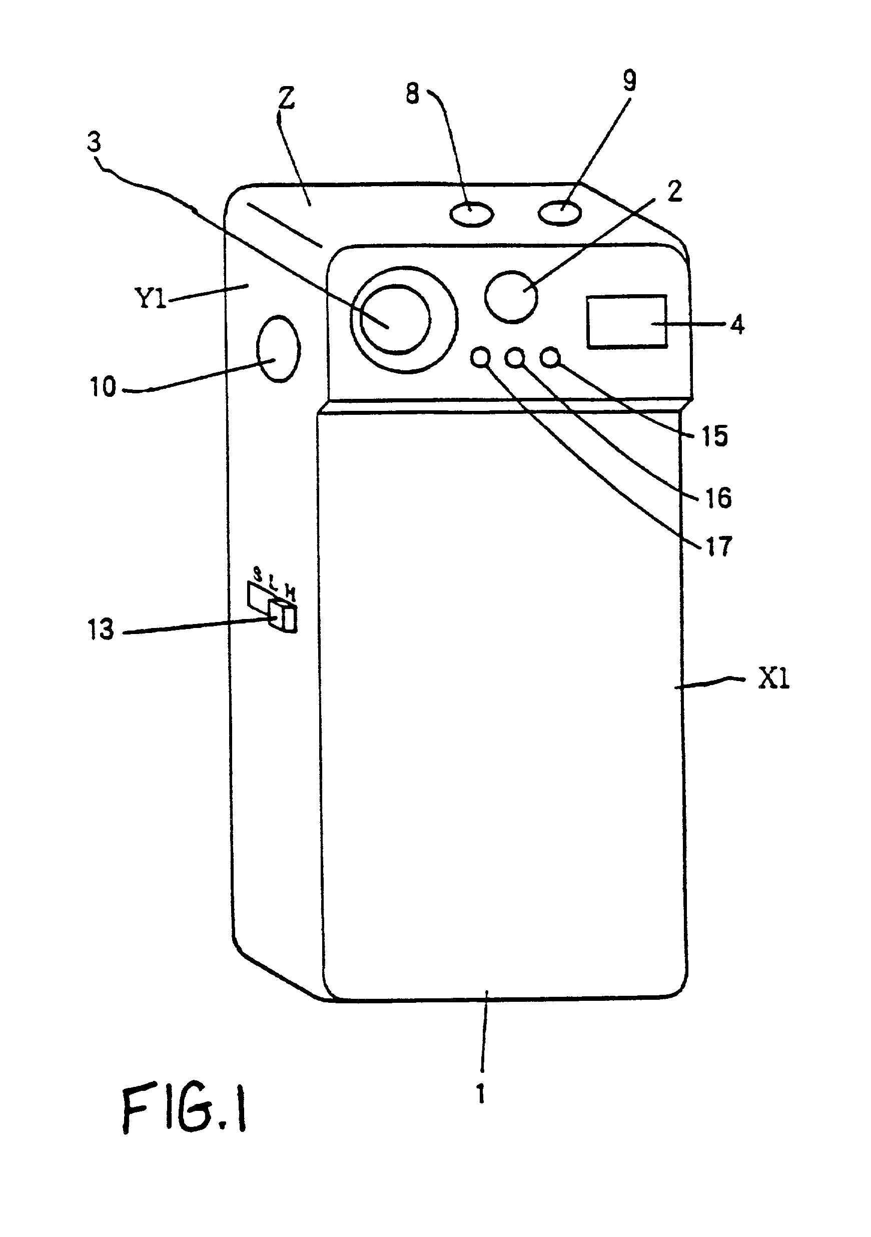
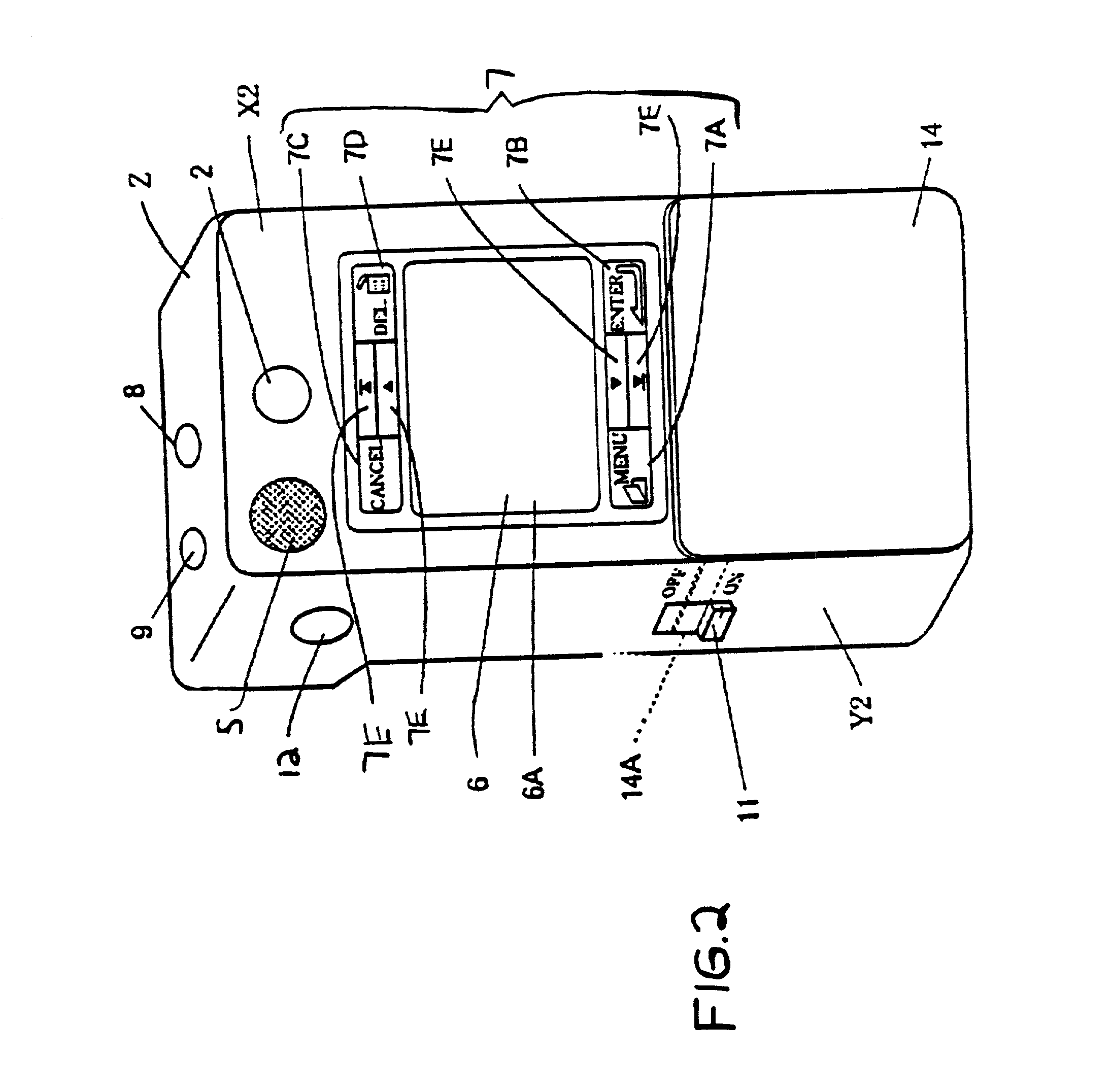
[0048]FIGS. 1 and 2 are perspective drawings showing the structure of one preferred embodiment of the electronic camera in accordance with the present invention. In the electronic camera of the preferred embodiment, when photographing an object, face X1 is oriented toward the object and face X2 is oriented toward the user. A viewfinder 2 is provided on face X1 to confirm the photographic range of the object. A photographic lens 3 that takes in the light image of the object and a flash component (strobe) 4 that flashes light to illuminate the object are also provided on face X1.

[0049]Furthermore, a red-eye reduction (RER) LED 15 is provided on face X1 that reduces red-eye by emitting light before the strobe 4 flashes when performing photography. A photometry device 16 performs photometry when action of the CCD 20 (FIG. 4) is halted and a colorimetry element 17 performs colorimetry when the CCD 20 is halted.

[0050]Meanwhile, viewfinder 2 and speaker 5 that outputs sound corresponding t...


PUM


Abstract

An information processing apparatus is provided that inputs and outputs images of different resolutions. When a resolution of a line drawing input via an interface is lower than the resolution of the monitor and the resolution of an image input via the interface is higher than the resolution of the monitor, the line drawing is provided to an interpolation circuit and the image is provided to a low-pass filter. The line-drawing is interpolated in the interpolation circuit and the image is pixel thinned by the low-pass filter. The line drawing and the image are displayed after being converted to the resolution of the monitor.

Description

RELATED PROVISIONAL APPLICATION[0001]This is a Continuation of application Ser. No. 08 / 972,742 filed Nov. 18, 1997. The entire disclosure of the prior application(s) is hereby incorporated by reference herein in its entirety.[0002]This nonprovisional application claims the benefit of U.S. Provisional Application No. 60 / 033,698, filed Dec. 20, 1996.INCORPORATION BY REFERENCE[0003]The disclosures of the following priority applications are herein incorporated by reference:[0004]Japanese Application No. 8-326545, filed Dec. 6, 1996; and[0005]Japanese Application No. 9-096906, filed Apr. 15, 1997.BACKGROUND OF THE INVENTION[0006]1. Field of Invention[0007]The present invention relates to an information processing apparatus such as an information processing apparatus that can efficiently perform input and display of images of different resolutions.[0008]2. Description of Related Art[0009]In recent years, electronic cameras have come to be used in place of cameras using film such that imag...

Claims


Application Information

Patent Timeline
Patent Type & Authority Patents(United States)
IPC IPC(8): H04N9/74G06F15/00H04N5/268G09G5/36G09G5/391G09G5/393
CPCG09G5/363G09G5/391G09G5/397G09G5/393G09G2340/02G09G2340/0407
Inventor EJIMA, SATOSHIHAMAMURA, AKIHIKO
Owner NIKON CORP
Learn More