
Projection-type video-image-displaying device

a video-image display and projection-type technology, applied in the direction of picture reproducers, picture reproducers using projection devices, instruments, etc., to achieve the effect of reducing device costs, reducing light loss, and displaying images more efficiently

Active Publication Date: 2015-10-15
MAXELL HLDG LTD
View PDF5 Cites 1 Cited by
  • Summary
  • Abstract
  • Description
  • Claims
  • Application Information

AI Technical Summary

Benefits of technology

The present invention aims to provide a projection-type video-image-displaying device that can improve the efficiency of light contributing to the display of an original image, while reducing the loss of light in the device, thereby displaying the image more efficiently and reducing costs of the device.

Problems solved by technology

That is, since the same color image with high resolution as that of a three-plate type is obtained by one liquid crystal panel, it is unnecessary to provide fine color filters on pixels on each panel.

Method used


Image

  • Projection-type video-image-displaying device
  • Projection-type video-image-displaying device
  • Projection-type video-image-displaying device

Examples


Embodiment Construction

[0013]Hereinafter, one embodiment of the present invention will be described in detail with reference to the accompanying drawings. In each drawing to be described later, the same reference numerals are given to the same parts. Further, in the following descriptions, descriptions of portions described once will be omitted to avoid overlapping.

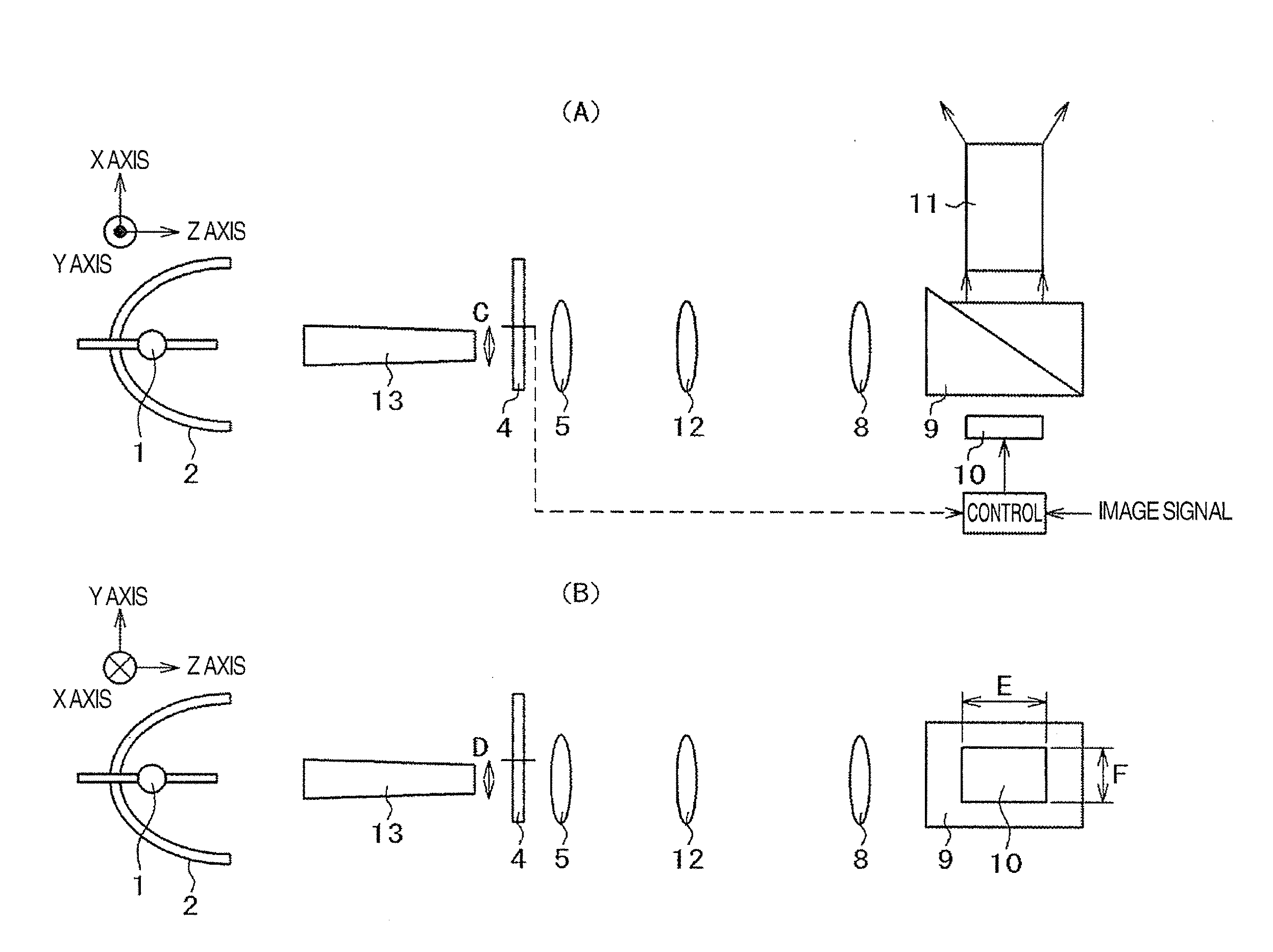
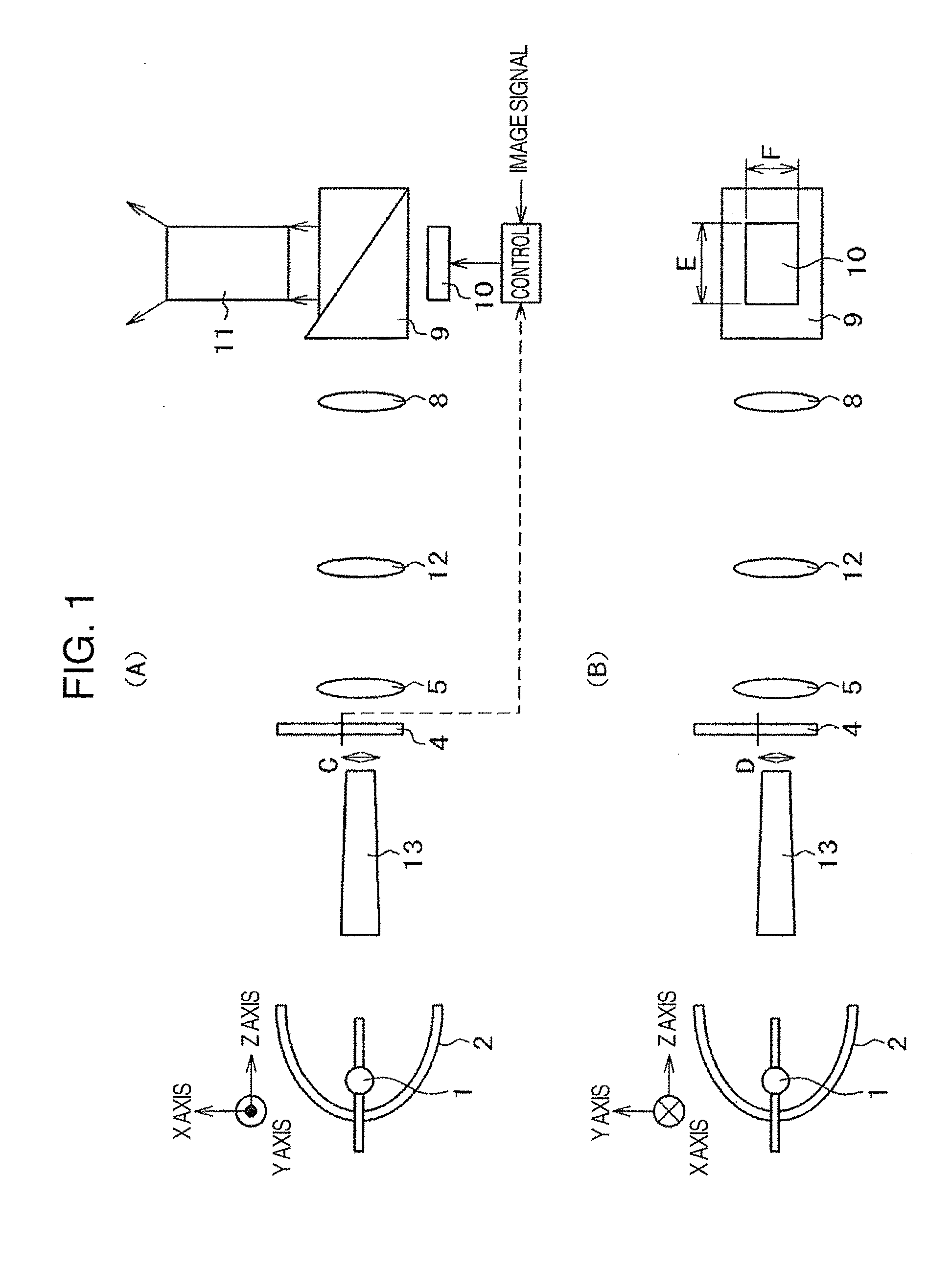
[0014]First, FIG. 1 are a top view (FIG. 1(A)) and a side view (FIG. 1(B)) illustrating one example of an essential part of a projection-type video-image-displaying device according to one embodiment of the present invention. Here, a local right-handed rectangular coordinate system is introduced into each figure. That is, in FIG. 1(A), a Z axis is used as a longitudinal direction of a light multiple reflecting element (rod lens), an X axis is used as an axis parallel to a page space in a surface perpendicular to the Z axis, and a Y axis is used as an axis toward a surface from a rear surface of the page space. Further, in FIG. 1(B), a Y axis is...


PUM


Abstract

A projection-type video-image-displaying device efficiently displays an image by reducing the loss of light in the device. The device is provided with a light source radiating white light, a rod lens, a rotary color filter, a DMD, illumination optical elements, a projection lens and a control device. The rod lens collects light from the light source and emits the light. The rotary color filter selectively transmits, from the white light, light of a specific color. The DMD modulates incident light in accordance with an image signal, and the illumination optical elements form illumination light for projection onto the DMD. The projection lens projects an image formed using the DMD. The control device synchronizes the rotary color filter with the image displayed by the DMD. The DMD is disposed in a substantially conjugate relationship with the light-emitting surface on the rotary color filter.

Description

TECHNICAL FIELD[0001]The present invention relates to a projection-type video-image-displaying device.BACKGROUND ART[0002]A projection-type video-image-displaying device which collects white light from a light source and forms a light-emitting surface, disposes a rotary color filter in the vicinity of the light-emitting surface, collects emitted light from the color filter and makes the light incident on one light modulation element, and projects an image formed by the light modulation element onto a screen by a projection lens, is already known by Patent Literature 1 described later. That is, since the same color image with high resolution as that of a three-plate type is obtained by one liquid crystal panel, it is unnecessary to provide fine color filters on pixels on each panel. Thereby, a yield of the liquid crystal panel can be improved and costs of the device can be reduced. Further, a control device which controls the rotation of the rotary color filter to be synchronized wit...

Claims


Application Information

Patent Timeline
Patent Type & Authority Applications(United States)
IPC IPC(8): H04N9/31G02B19/00G02B26/00
CPCH04N9/3114H04N9/3182G02B19/0047G02B26/008G02B27/126G03B21/008G03B21/208G03B33/08H04N9/3152G02B19/0019G02B27/1033
Inventor HIRATA, KOJIKIMURA, NOBUYUKIINADACHI, YURIKO
Owner MAXELL HLDG LTD
Learn More