
Projection display

Inactive Publication Date: 2006-02-02
OLYMPUS CORP
View PDF2 Cites 3 Cited by
  • Summary
  • Abstract
  • Description
  • Claims
  • Application Information

AI Technical Summary

Benefits of technology

[0012] In view of such problems with the prior art as described above, an object of the invention is to provide a projection display for projection of a viewing pupil having a limited area, which permits a viewer to take immediate notice of a viewer's own eye being off the limited pupil area so as to ensure facilitated viewing of a bright, normal projection image.
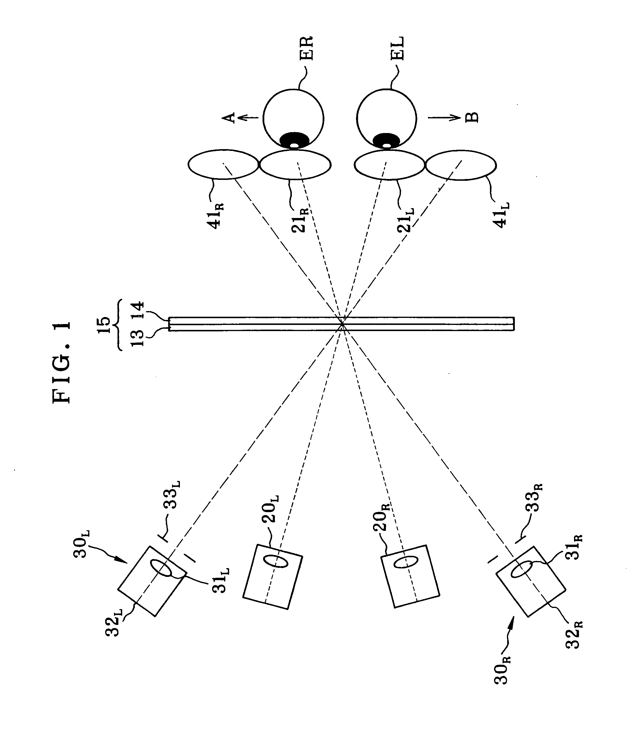
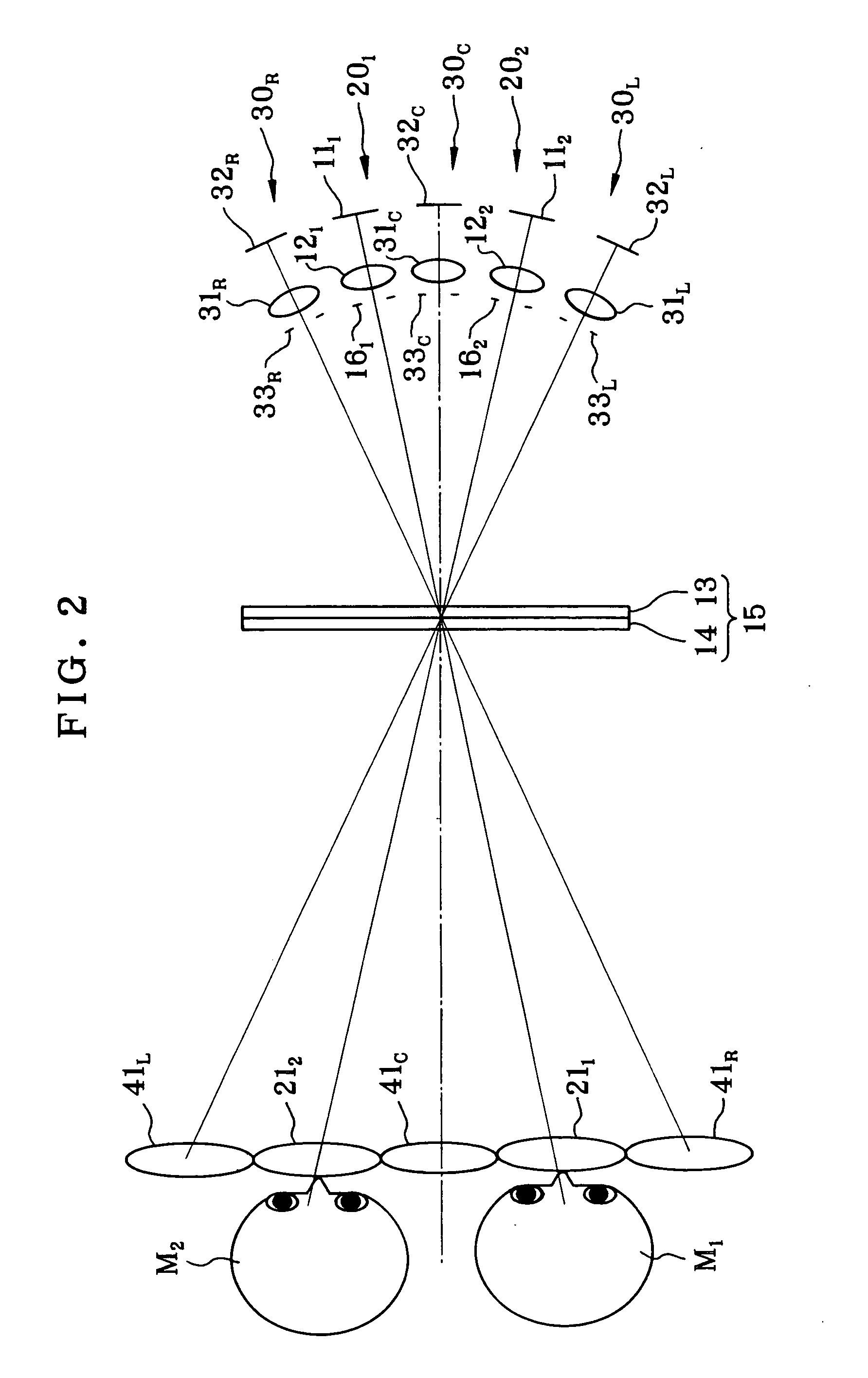
[0018] With the inventive arrangement of the projection display wherein a misalignment warning pupil is adjacent to or overlaps partly with said viewing pupil via said display panel, and a misalignment warning projector for issuing a misalignment warning is located on said display panel and adjacent to at least one of said projection optical systems, it is possible for the viewer to take immediate notice of his or her own eye being off the limited viewing area, so that viewing of a bright, normal projected image can be facilitated.

Problems solved by technology

With such projection displays designed to project the viewing pupil having a limited area, it is impossible to view any bright, normal projected image as the viewer's eyes are off that limited pupil area.
However, as long as one of both eyes of the viewer stays in the viewing pupil area especially in the horizontal direction, it is not necessarily easy for the viewer to take notice of another eye being off the limited pupil area.

Method used


Image

  • Projection display
  • Projection display
  • Projection display

Examples


Embodiment Construction

[0026] The projection display of the invention is now explained with reference to its preferred embodiments.

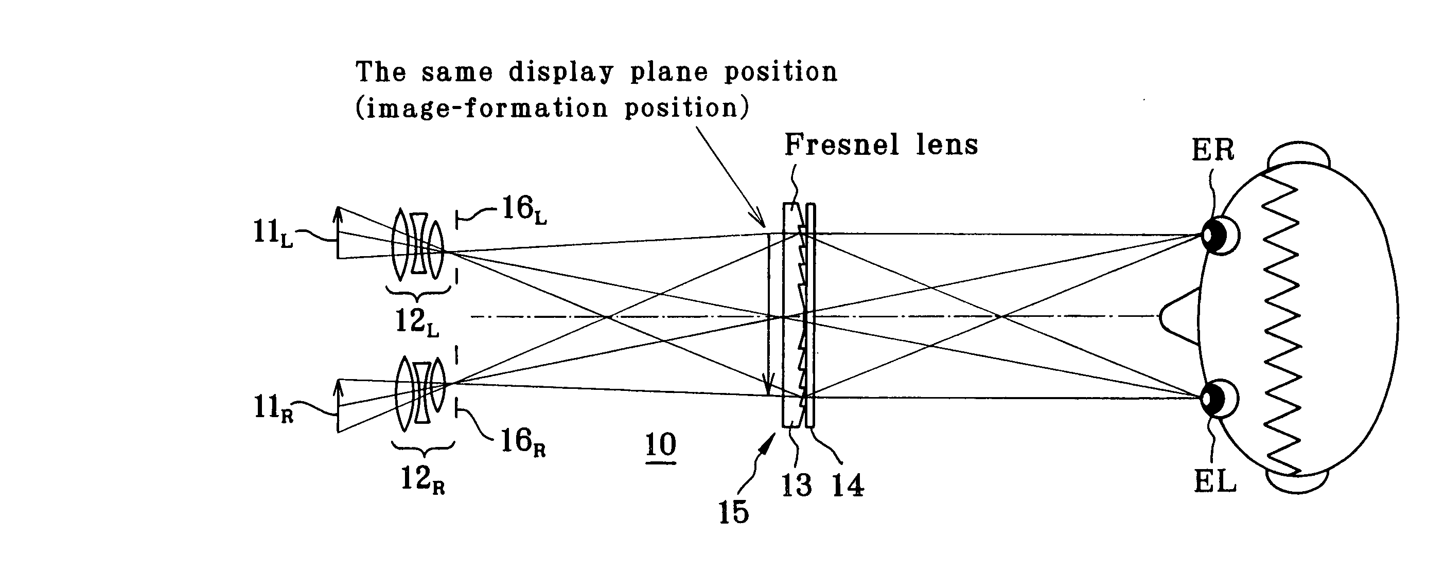
[0027]FIG. 4 is generally illustrative in construction of one embodiment of the invention, specifically a 3D projection display 10 wherein two left and right 2D parallactic images appearing on two 2D display devices 11L, 11R are simultaneously projected onto a display panel 15 for 3D representation. Here FIG. 4(a) is illustrative in schematic of the construction of a transmission type projection display, and FIG. 4(b) is illustrative in schematic of the construction of a reflection type projection display. In FIG. 4(b), for convenience, only the right-eye arrangement is shown; the left-eye arrangement is not shown.

[0028] The 3D projection displays 10 shown in FIGS. 4(a) and 4(b) are each made up of display devices 11L, 11R, projection optical systems 12L, 12R, an image-formation optical system 13, and a diffuser plate 14 that is in contact with, or slightly spaced away from,...


PUM


Abstract

The invention concerns a projection display for the projection of a viewing pupil having a limited area, which enables a viewer to take notice of the eye of the viewer per se being off the limited pupil area. The projection display comprises a display device, a projection optical system that has an aperture and is adapted to magnify and project an image appearing on the display device, and a display panel 15 including image-formation means 13 located near an image projected through the projection optical system for formation at a viewing pupil position of an aperture image of the projection optical system and diffuser means 14 that has scatter action and is adapted to magnify the aperture image of the projection optical system into viewing pupils 21L, 21R. Misalignment warning pupils 41L, 41R are adjacent to or overlap partly with the viewing pupils 21L, 21R via the display panel 15, and misalignment warning projectors 30L, 30R for issuing a misalignment warning are located on the display panel and adjacent to at least one of the projection optical systems.

Description

[0001] This application claims benefit of Japanese Application No. 2004-221211 filed in Japan on 7.29, 2004, the contents of which are incorporated by this reference. BACKGROUND OF THE INVENTION [0002] The present invention relates generally to a projection display, and more particularly to a projection display of the type that can project a viewing pupil having a limited area for the purpose of viewing a bright projected image. [0003] The applicant has already filed patent applications concerning the inventions set forth in patent publications 1, 2, 3 or the like to come up with a 2D projection display, a 3D projection display, a projection display that enables a plurality of viewers to view separate projected images, or the like, each of which comprises a single or plural display devices, a single or plural projection optical systems including an aperture (exit pupil) for magnifying and projecting an image appearing on each display device, and a display panel comprising a Fresnel ...

Claims


Application Information

Patent Timeline
IPC IPC(8): G03B21/00
CPCG03B35/20H04N13/0402G03B35/24H04N13/302
Inventor TOGINO, TAKAYOSHI
Owner OLYMPUS CORP
Learn More