
Imaging Apparatus

Inactive Publication Date: 2015-11-19
MURPHY RICHARD B
View PDF9 Cites 6 Cited by
  • Summary
  • Abstract
  • Description
  • Claims
  • Application Information

AI Technical Summary

Benefits of technology

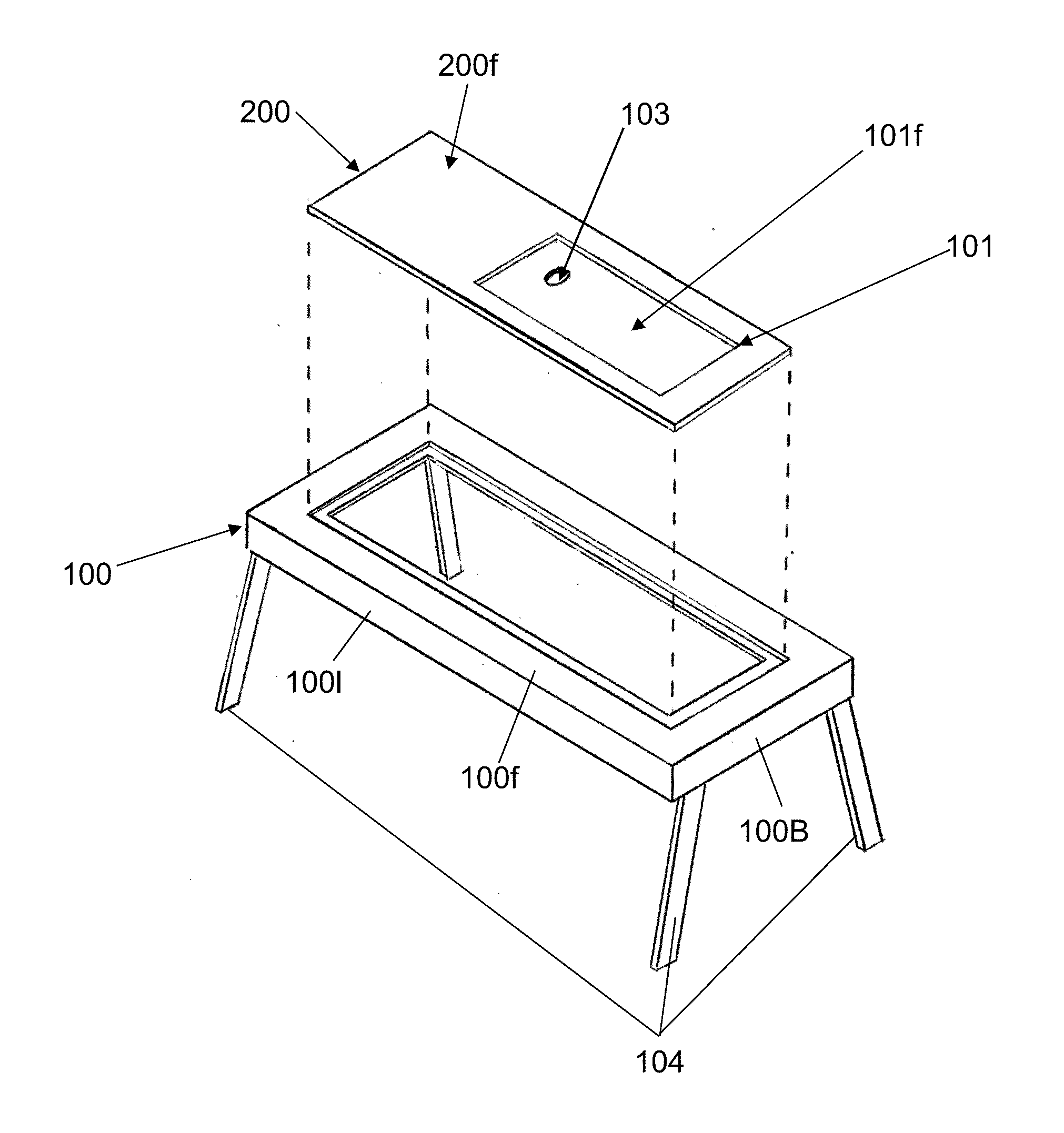
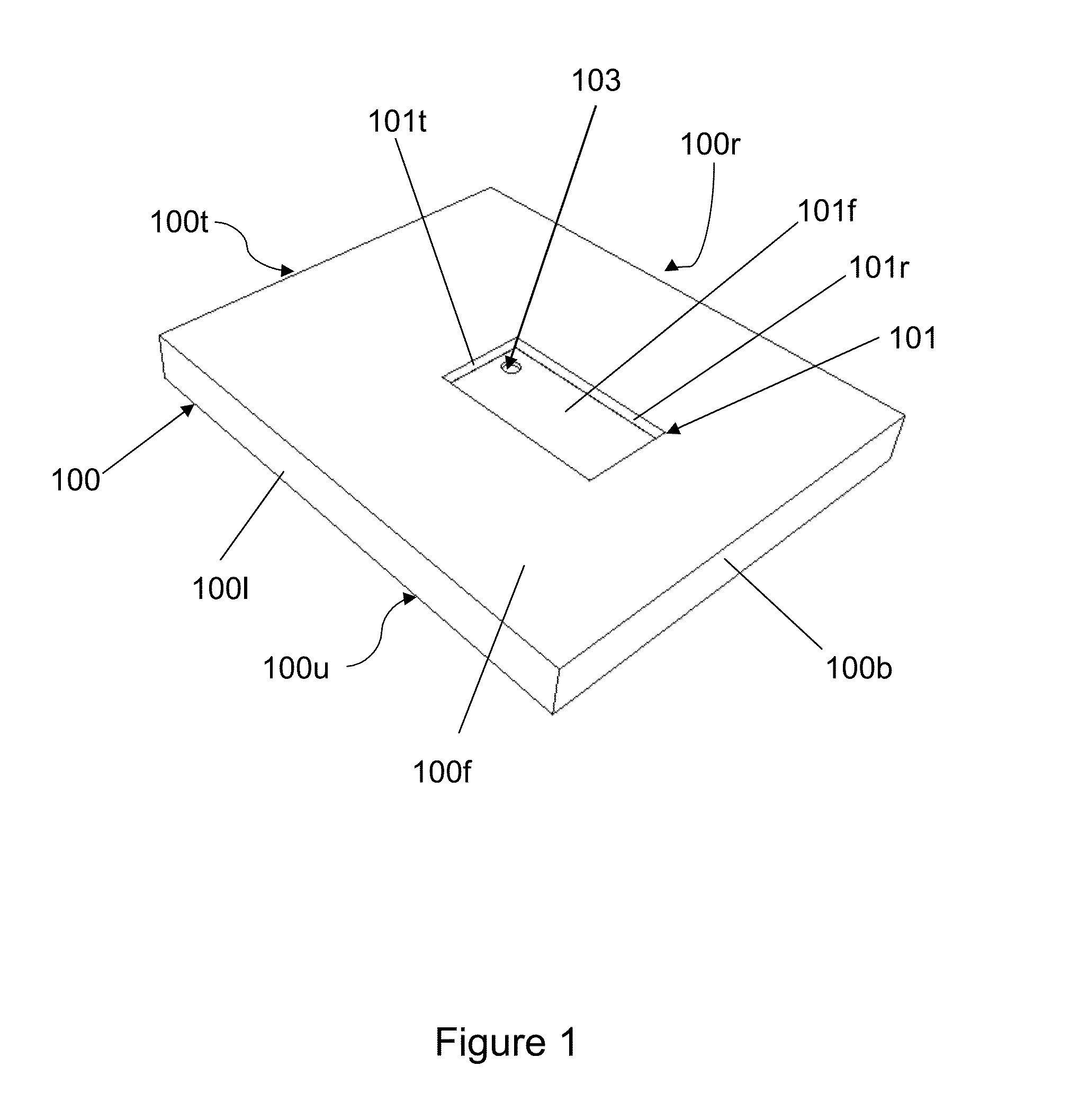
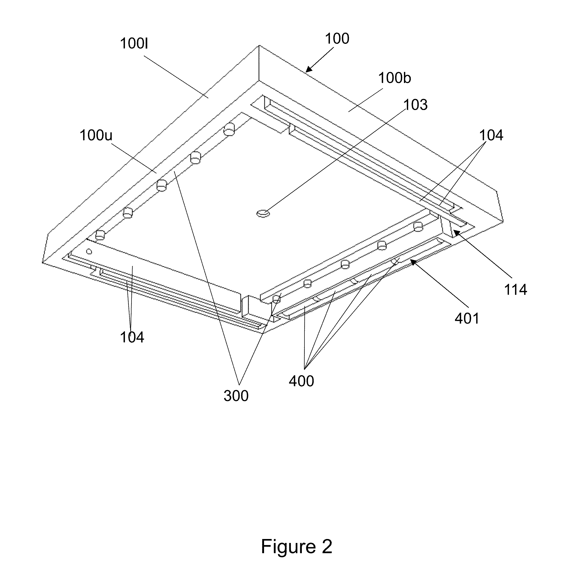
[0005]The present invention provides an apparatus to facilitate the imaging of objec

Problems solved by technology

However, these devices are conventionally large and expensive devices primarily designed for use in a fixed location.

Method used


Image

  • Imaging Apparatus
  • Imaging Apparatus
  • Imaging Apparatus

Examples


Embodiment Construction

[0016]Detailed embodiments of the present invention are disclosed herein. However, it is to be understood that the disclosed embodiments are merely illustrative of the invention that may be embodied in various forms. In addition, each of the examples given in connection with the various embodiments of the invention are intended to be illustrative, and not restrictive. Further, the figures are not necessarily to scale, some features may be exaggerated to show details of particular components. Therefore, specific structural and functional details disclosed herein are not to be interpreted as limiting, but merely as a representative basis for teaching one skilled in the art to variously employ the present invention. Furthermore, any section headings are merely for convenience of the reader and not intended to provide a limitation on the scope of the disclosure with respect to any feature of utility of the present invention.

[0017]Camera:

[0018]As used herein the term “camera” refers to t...


PUM


Abstract

The present invention provides a system to facilitate the imaging of objects using a portable computing device equipped with an imaging system invention providing a means to stably position a portable computing device in an elevated position above a surface to enable the rear facing camera of said device to image objects positioned thereunder. The invention further provides illumination systems and lenses to facilitate imaging.

Description

CROSS REFERENCE TO OTHER APPLICATIONS[0001]The present application claims the benefit under 35 USC 119(e) of U.S. Provisional Patent Application Ser. No. 61 / 996,672 filed May 14, 2014, the entire teaching of which is herein incorporated by reference.BACKGROUND OF THE INVENTION[0002]It is a common need in business to be able to create digital versions of physical documents such as business correspondence, articles, and photographs. Digital versions of tangible documents have myriad advantages such as compact storage, ease of transport, ability to convert to digital form via optical character recognition technologies, and ease of communication. The proliferation of multifunction printer / scanners facilitate the digital imaging of such materials recognize and address this need to some extent. Additionally, there are commercially available camera-based systems that are specially designed for use in imaging documents such as those provided by the ELMO Corporation. However, these devices a...

Claims


Application Information

Patent Timeline
IPC IPC(8): G06K9/82H04N1/00G06K9/22G06T1/00G06F17/30G06K9/20
CPCG06K9/82H04N2201/0096G06F17/30253G06K9/2027G06K9/22G06T1/0007H04N1/00307G06K2209/01G06T2207/10004G06T2207/10152G06T2207/30176H04N2201/0422H04N2201/0436H04N2101/00H04N2201/0084G06F17/30011H04N1/00562H04N1/19594G06F16/93G06F16/5846G03B17/561
Inventor MURPHY, RICHARD B.
Owner MURPHY RICHARD B
Learn More