Radiation scanning units with reduced detector requirements

a technology of radiation scanning and detector requirements, applied in the direction of material analysis using wave/particle radiation, instruments, applications, etc., can solve the problems of high system cost, deterioration of detector electronics, and high maintenance cost of the system

Inactive Publication Date: 2006-02-02
VAREX IMAGING CORP
View PDF98 Cites 40 Cited by
  • Summary
  • Abstract
  • Description
  • Claims
  • Application Information

AI Technical Summary

Benefits of technology

[0031] As used herein, the term “at least one of” means any one or more of the following.

Problems solved by technology

Detectors, which are expensive components of a CT scanning system, contribute to the high cost of the system.
Deterioration of detector electronics due to exposure to the high radiation energies required to penetrate cargo conveyances, despite shielding, contributes to the maintenance costs of the system.

Method used


Image

  • Radiation scanning units with reduced detector requirements
  • Radiation scanning units with reduced detector requirements
  • Radiation scanning units with reduced detector requirements

Examples


Embodiment Construction

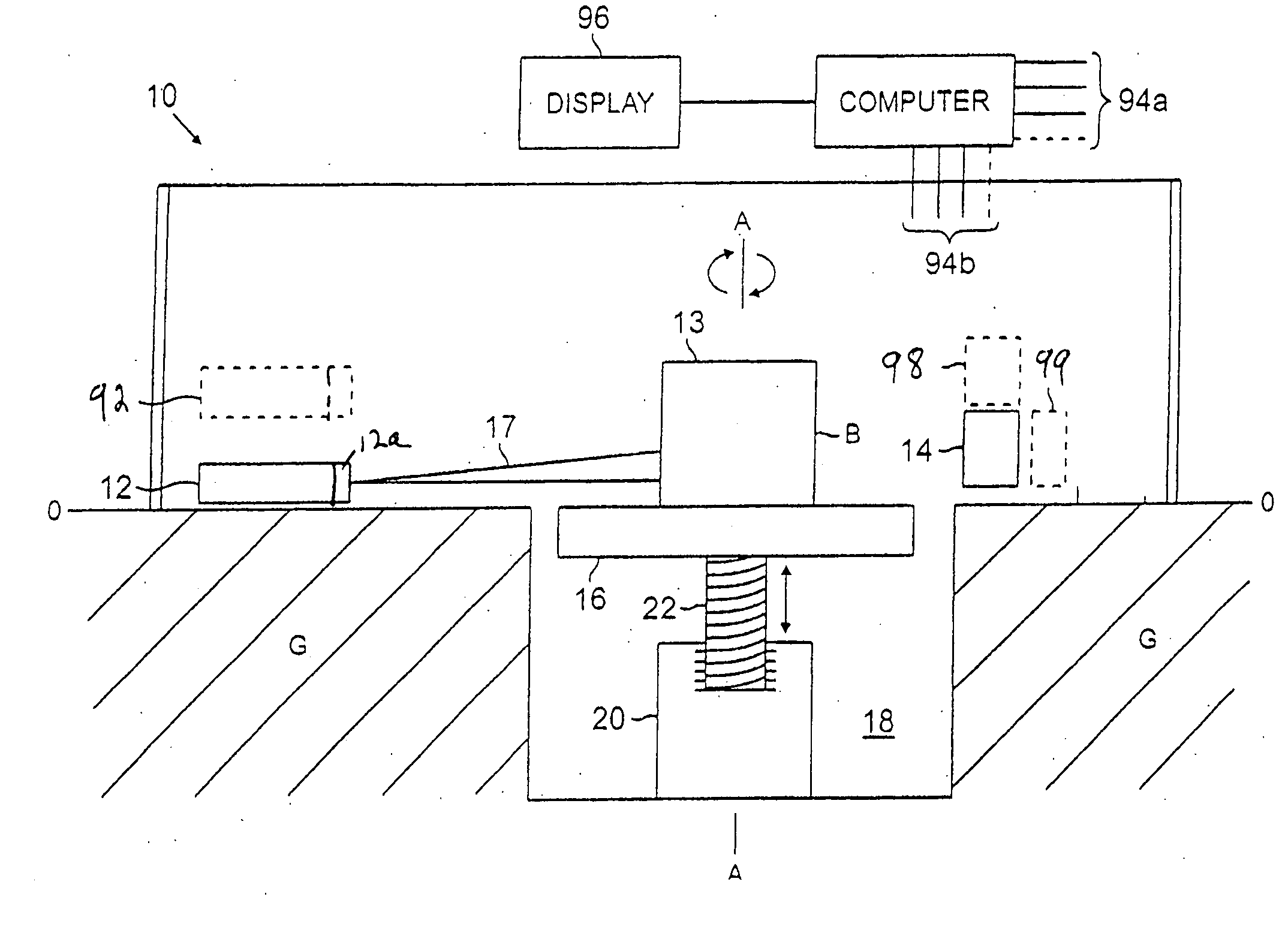
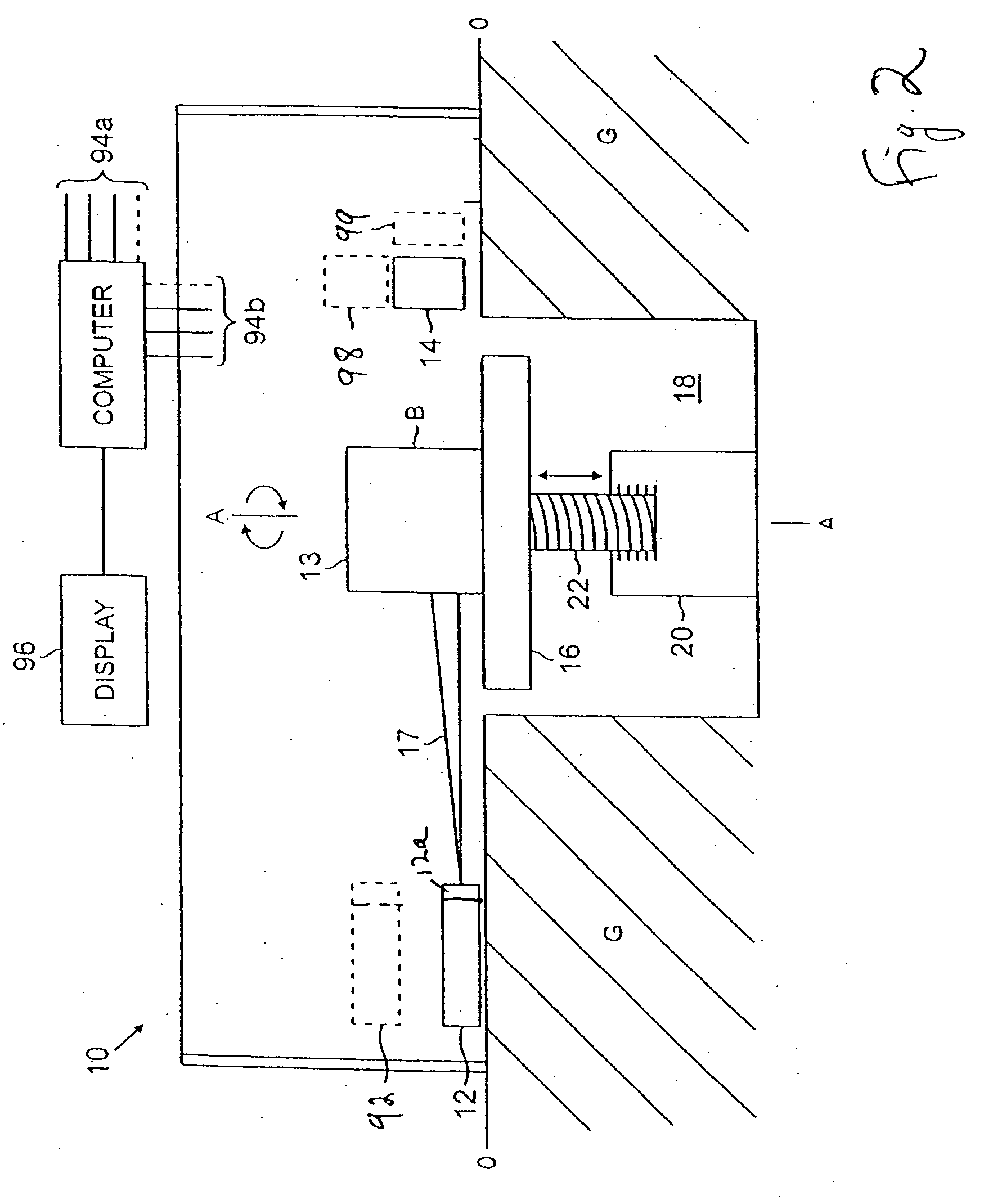
[0048] In an embodiment of the present invention, the length of a detector array is reduced by using a partial radiation beam to scan the object. In another embodiment, the number of detector modules in a detector array is reduced by providing gaps along the length of the detector array and compensating for the lack of data collected in the gaps.

[0049]FIG. 2 is a side view of an example of a scanning unit 10 that may be configured to implement embodiments of the present invention. In this example, the scanning unit 10 comprises a source of radiation 12, such as a source of X-ray radiation, to irradiate an object 13 being scanned, a detector 14 to detect radiation transmitted through the object 13 and a rotating / vertically displaceable platform 16 to support and position the object during scanning. The rotating / vertically displaceable platform 16 is between the source 12 and the detector 14. A collimator 12a collimates the generated radiation into a horizontally diverging beam 17 of...


PUM

PropertyMeasurementUnit
widthaaaaaaaaaa
thicknessaaaaaaaaaa
median energyaaaaaaaaaa

Abstract

In one embodiment, a scanning unit for inspecting cargo conveyances uses a partial radiation beam and a detector of reduced length. In another embodiment, a scanning unit for inspecting objects comprises a detector with gaps along its expanse. In both cases, the cost of the scanning system may be reduced. The object, the source, and or the detector may be moved to enable generation of computed tomographic images. Methods are disclosed, as well.

Description

RELATED APPLICATION [0001] The present application is a continuation-in-part of application Ser. No. 10 / 310,060, which was filed on Dec. 4, 2002, is assigned to the assignee of the present invention, and is incorporated by reference, herein.FIELD OF THE INVENTION [0002] Radiation scanning of objects and, more particularly, radiation scanning of objects to reconstruct computed tomographic images. BACKGROUND OF THE INVENTION [0003] Radiation is commonly used in the non-invasive inspection of objects such as luggage, bags, briefcases and the like, to identify hidden contraband at airports and public buildings. The contraband may include hidden guns, knives, explosive devices and illegal drugs, for example. [0004] To obtain additional information about the contents of the luggage and other objects, detectors may be provided to detect scattered radiation, as described in U.S. Pat. No. 5,642,394, for example. Systems may combine detection of scattered radiation with the detection of trans...

Claims


Application Information

Patent Timeline
Patent Type & Authority Applications(United States)
IPC IPC(8): G01N23/04
CPCG01N23/046G01N2223/419G01V5/005G01V5/0008
Inventor SEPPI, EDWARD J.
Owner VAREX IMAGING CORP
Why Eureka
Try Eureka