
Real time fiber optic matrix switch interconnection

a fiber optic matrix switch and real-time technology, applied in the field of communication systems, can solve the problems of unsatisfactory results for the navy, inability to maintain separate systems for all fielded versions, and significant command, control and personnel training, and achieve the effect of reducing the number of fielded versions

Inactive Publication Date: 2006-02-02
COUNTRY CLUB BANK N A
View PDF9 Cites 5 Cited by
  • Summary
  • Abstract
  • Description
  • Claims
  • Application Information

AI Technical Summary

Benefits of technology

[0025] It is an aspect of the invention to provide improved elements and arrangements thereof in a real time fiber optic matrix switch interconnection for the purposes described which is inexpensive, dependable, and fully effective in accomplishing its intended purposes.

Problems solved by technology

These circumstances present the Navy with significant command, control, and personnel training, qualification, and simulation challenges.
The wide range of existing hardware and software configurations render it impractical and cost prohibitive to maintain separate systems for all fielded versions.
Previous technology for achieving this electronic “linking together” of disparately located shore-based training equipment has proved unsatisfactory to the Navy.
The monumental size, length, and amount of cable required to connect the various pieces of equipment comprising a specific NTDS shipboard configuration's weapons systems, computers, transmitters, receivers, cryptographic equipment, radars, sensors, magnetic tapes, disks, displays and consoles is unwieldy.
Earlier techniques also were prone to generating delays in receipt of data between sender and recipient components that destroyed the instant, “real time” mimicry of shipboard systems that the tactical computer programs require to function properly, and that are so important to the training that occurs in these facilities.
There was also an accompanying degradation in signal integrity that further diminished the capability of the electronic configuration to adequately mimic its shipboard counterpart.

Method used


Image

  • Real time fiber optic matrix switch interconnection
  • Real time fiber optic matrix switch interconnection
  • Real time fiber optic matrix switch interconnection

Examples


Embodiment Construction

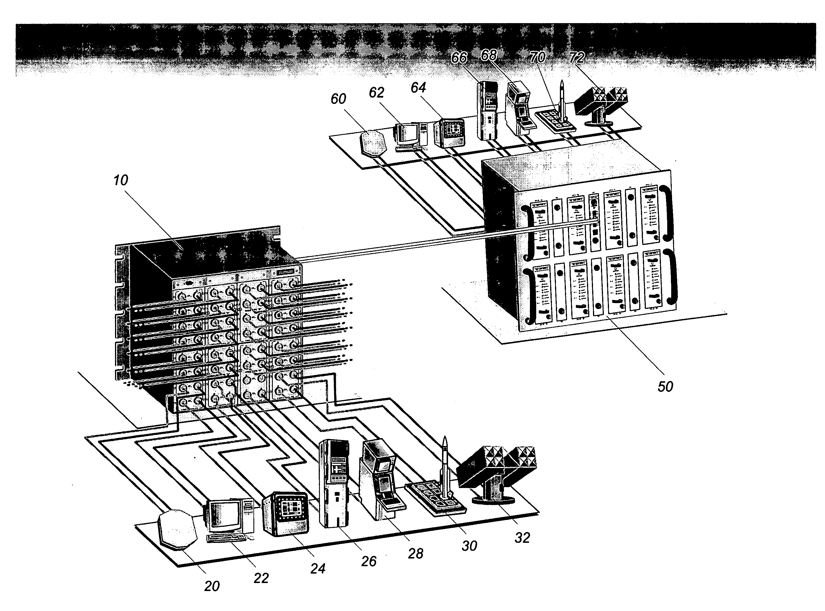
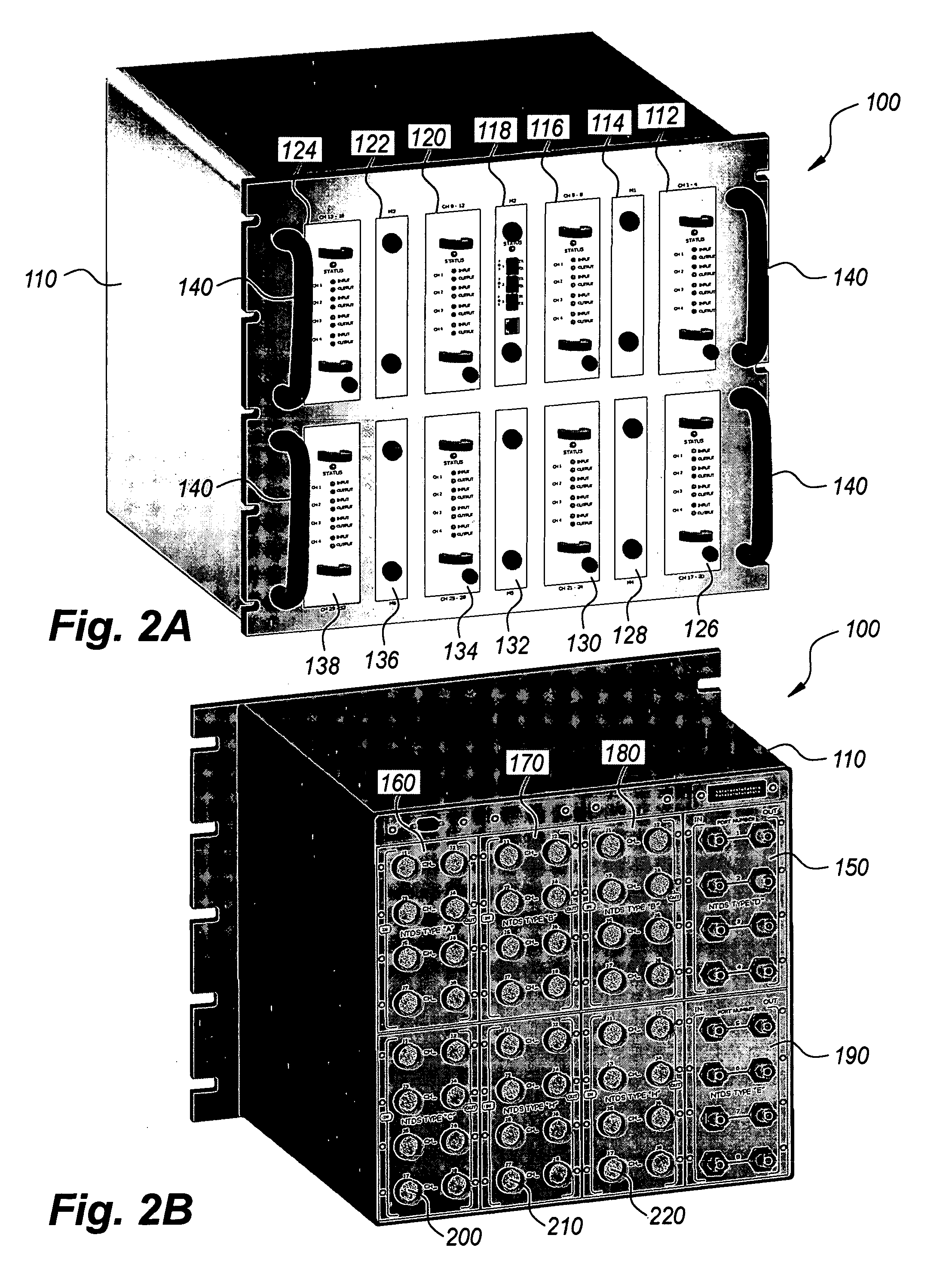
[0035] The present invention is a real time fiber optic matrix switch interconnection. The invention disclosed herein is, of course, susceptible of embodiment in many different forms. Shown in the drawings and described herein below in detail are preferred embodiments of the invention. It is to be understood, however, that the present disclosure is an exemplification of the principles of the invention and does not limit the invention to the illustrated embodiments.

[0036] Referring to the drawings, FIG. 1 illustrates a real time fiber optic matrix switch interconnection between two inventive matrix switches 10 and 50 configured according to the invention. The arrangement shown in FIG. 1 is representative of two shore-based training facilities located at disparate physical locations that are interconnected with a real time fiber optic matrix switch interconnection that can easily mimic specific on-board systems so that personnel undergoing training may encounter systems on a particul...


PUM


Abstract

A real time fiber optic matrix switch includes at least one matrix switch port and a controller card. The controller card is configured to recognize communication protocols associated with any of the Type A-H and J signals of the Naval Tactical Data System (NTDS), and to enable the communication of information between the matrix switch and interconnected peripheral devices, as well as any interconnected matrix switches. The controller card is externally programmed by a digital logic program that multiplexes data streams of received signal types to one data stream, converts the multiplexed data stream to an optical signal, transmits the optical signal, receives the transmitted optical signal, transforms the received optical signal to an electric signal, demultiplexes the electric signal, validates the demultiplexed electric signal, and acknowledges the validated demultiplexed electric signal.

Description

BACKGROUND OF THE INVENTION [0001] 1. Field of the Invention [0002] The present invention relates generally to communication systems and, more particularly, to a real time fiber optic matrix switch interconnection that mimics the specific system platform or generation of equipment that personnel undergoing training will encounter on a particular ship to which they are being assigned, or into which any new hardware or software being tested and evaluated must be integrated. [0003]2. Description of the Related Art [0004] In combat, a fleet of U.S. Navy ships is frequently involved in close-range offensive and defensive combat. During such close range combat, the shipboard Combat Information Center (“CIC”) is the focus of all naval and joint air defense management activity, and is the locus of all rapid, complex tactical decision-making by ship commanders. [0005] The Naval Tactical Data System (“NTDS”) is an electronic shipboard combat data communication system that is used by the vario...

Claims


Application Information

Patent Timeline
IPC IPC(8): H04J14/00
CPCH04L49/101H04L49/357H04L49/30H04L49/254
Inventor ERISMAN, DAVID E.JAEGER, DOUGLAS J.RENICH, STEVEN A.
Owner COUNTRY CLUB BANK N A
Learn More