
Axial flow combine harvester with adaptable threshing unit

a combine harvester and threshing unit technology, applied in the field of agricultural harvesters, can solve the problems of uneven crop flow, axial flow units are particularly prone to plugging, etc., and achieve the effects of reducing the risk of crop wounding, and reducing the aggressive threshing section

Inactive Publication Date: 2006-02-02
CNH IND AMERICA LLC
View PDF8 Cites 5 Cited by
  • Summary
  • Abstract
  • Description
  • Claims
  • Application Information

AI Technical Summary

Benefits of technology

[0004] Generally, each rotor includes a threshing section, which immediately follows an infeed section, the infeed section generally delivering the crop material to the rotor. A separating section follows the threshing section. The threshing section has a plurality of sets of rasp bars, such as a leading rasp bar and a trailing rasp bar, which are provided at predetermined positions around the periphery of the threshing section of the rotor. The crop material is threshed along the longitudinal extent defined by the rotor, which results in increased harvesting efficiency because a higher degree of separation is reached and grain losses are reduced.
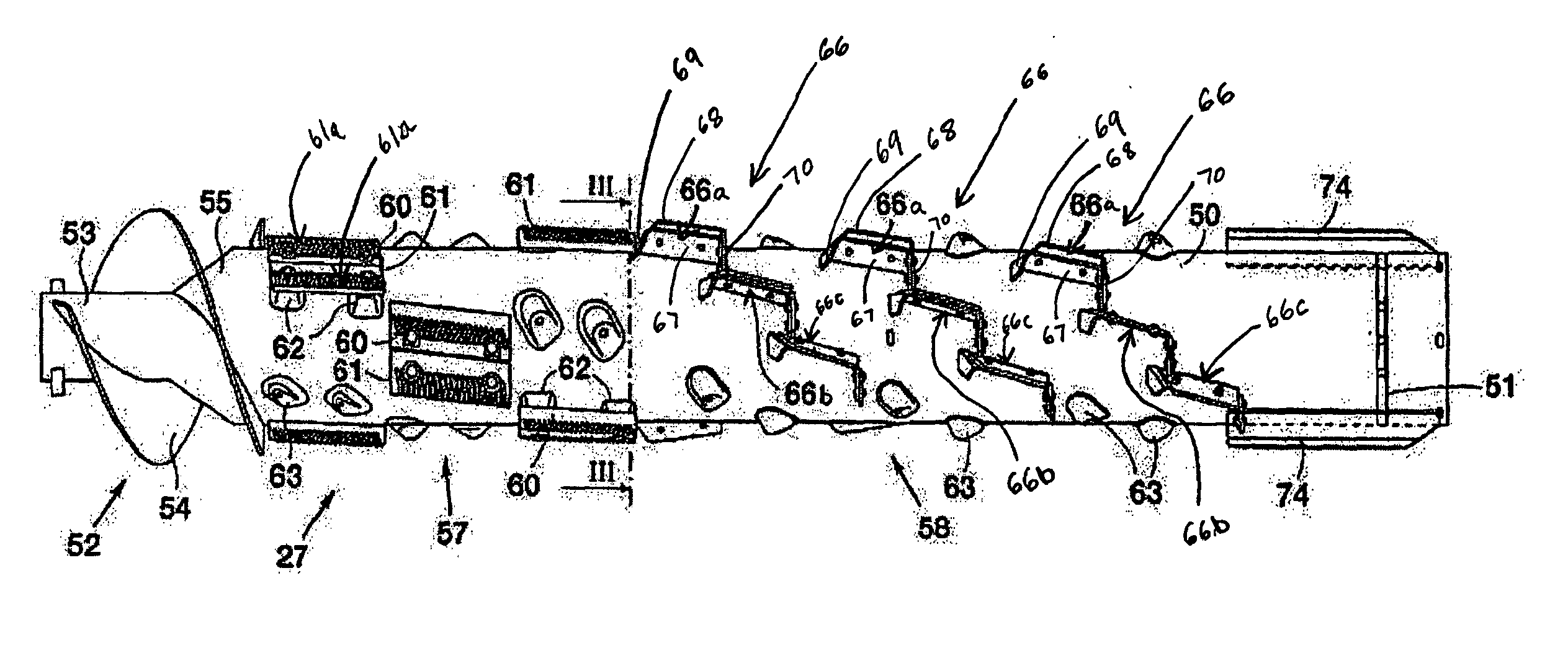
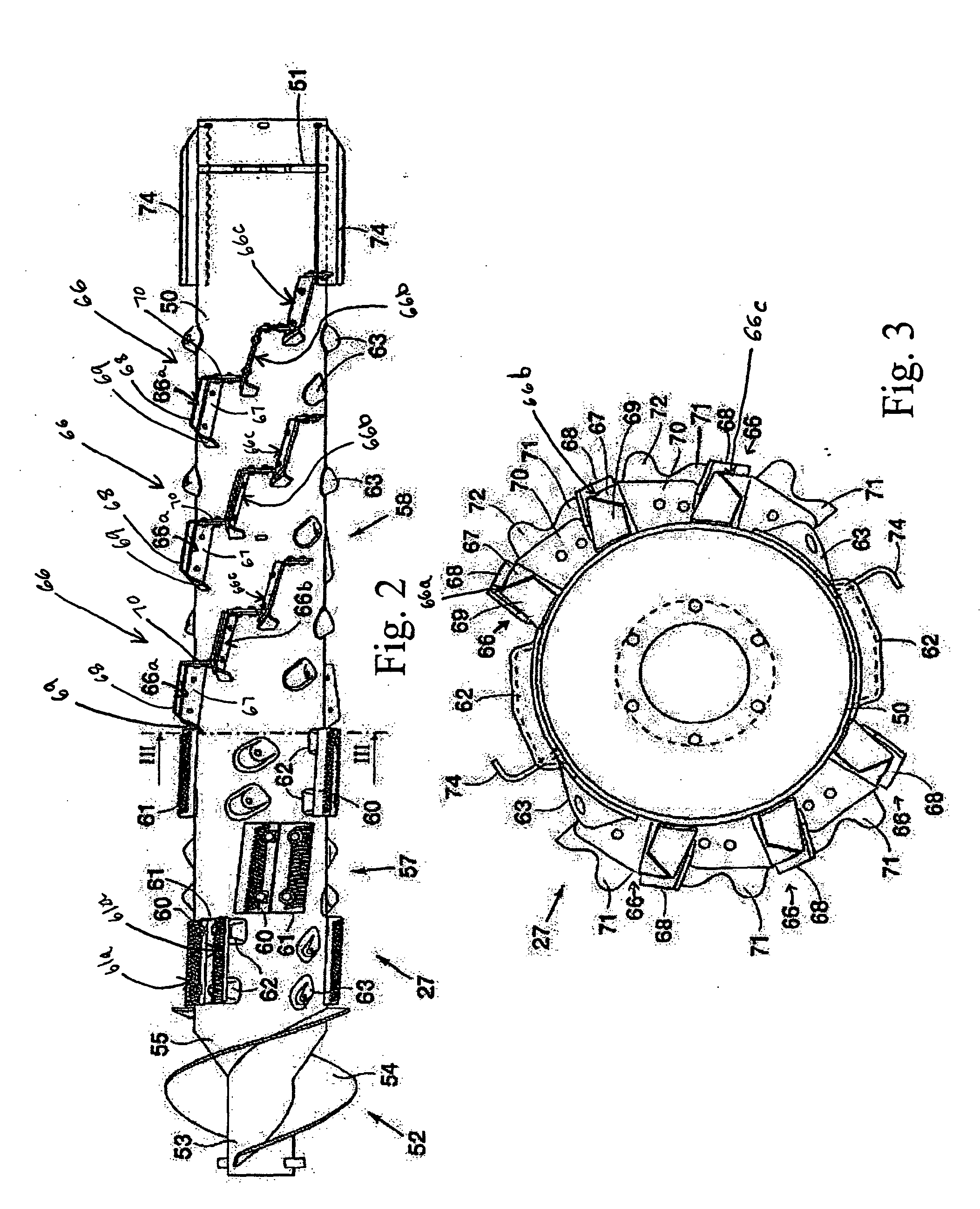
[0007] With a view toward mitigating the foregoing disadvantage, the present invention provides an axial flow combine harvester comprising a rotor having a thresher section and a separator section. The thresher section includes pairs of rasp bars, such as a leading rasp bar and a trailing rasp bar. The pairs of rasp bars are preferably staggered from one another along a helical path of the rotor. Individual trailing rasp bars of at least each of the pairs of rasp bars are removable to render the action of the thresher section less aggressive. More specifically, a flow deflector plate can be mounted in the position of the removed trailing rasp bar to guide the crop flow continuously from the remaining, leading rasp bar into the separator section of the rotor.
[0018]FIG. 7 shows a detail of the rotor of FIG. 6 drawn to enlarged scale illustrating a crop flow deflector position in lieu of one of the removed rasp bars so as to improve crop flow and reduce the risk of the crop being wound around the rotor and creating a blockage.DETAILED

Problems solved by technology

However, when the crop contains green material, such axial flow units can be particularly prone to plugging by slugs of accumulated crop material that lodge between the leading and trailing rasp bars of the rotor and the concaves.
However, removal of every trailing rasp bar from the rotor, especially from near the end of the thresher section adjacent the separator section, can result in an uneven crop flow from the thresher section into the separator section of the rotor.
This uneven crop flow can also cause plugging.

Method used


Image

  • Axial flow combine harvester with adaptable threshing unit
  • Axial flow combine harvester with adaptable threshing unit
  • Axial flow combine harvester with adaptable threshing unit

Examples


Embodiment Construction

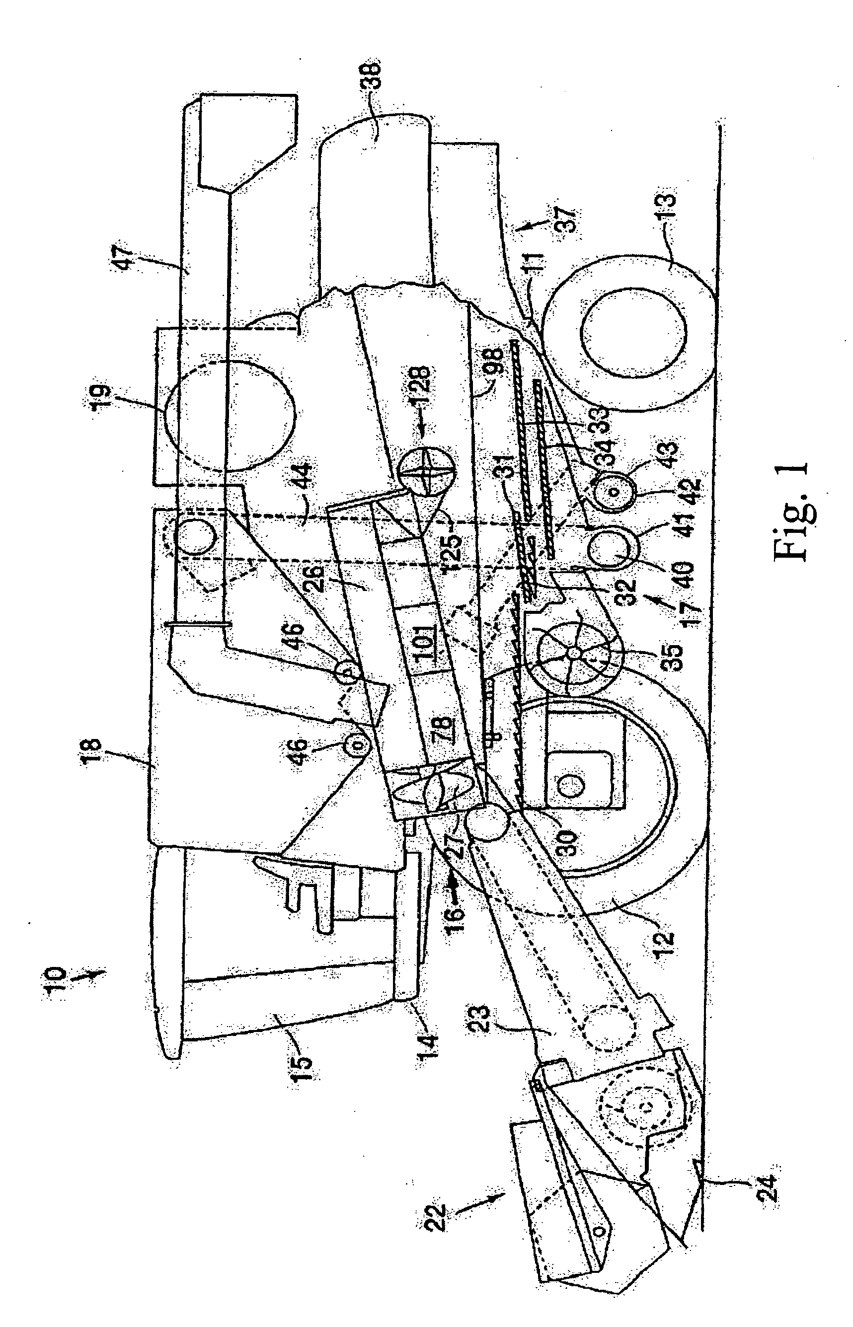
[0019] The terms “grain”, “straw” and “tailings” are used principally throughout this specification for convenience and it is to be understood that these terms are not intended to be limiting. Thus “grain” refers to that part of the crop material which is threshed and separated from the discardable part of the crop material, which is referred to as “straw”. Incompletely threshed crop material is referred to as “tailings”. Also the terms “forward”, “rearward”, “left” and “right”, when used in connection with the combine harvester and / or components thereof, are determined with reference to the direction of forward operative travel of the combine harvester, but again, they should not be construed as limiting. The terms “longitudinal” and “transverse” are determined with reference to the fore-and-aft direction of the harvester and are equally not to be construed as limiting.

[0020] The combine harvester 10 shown in FIG. 1 of the accompanying drawings is of the axial-flow type, wherein c...


PUM


Abstract

An axial flow combine harvester is described which comprises a rotor having a thresher section and a separator section. The thresher section includes pairs of rasp bars, which are staggered from one another along a helical path. Individual rasp bars of the pairs of rasp bars are located adjacent to the separator section of the rotor. The individual rasp bars are removable to render the action of the thresher section less aggressive. To reduce the risk of plugging when a trailing rasp bar is removed, a flow deflector plate is mountable in place of the removable rasp bars so as to guide the crop flow continuously from the remaining rasp bar to the infeed end of the separator section of the rotor.

Description

CROSS REFERENCE TO RELATED APPLICATIONS [0001] This application is a continuation of and claims priority to pending U.S. application Ser. No. 10 / 863,691, filed on Jun. 4, 2004, which claims priority under 35 U.S.C. § 119 to GB 0325904.1, filed on Nov. 5, 2003, entitled “Axial Flow Combine Harvester with Adaptable Threshing Unit” and having Eric P. J. Van Quekelberghe and Eric Crornheecke as the Inventors. The full disclosure of U.S. application Ser. No. 10 / 863,691 and of GB 0325904.1 are hereby incorporated herein by reference in their entirety.FIELD OF THE INVENTION [0002] The present invention relates to agricultural harvesters and, more particularly, to axial flow combine harvesters having a threshing and separating unit with at least one generally longitudinally arranged rotor for advancing crop material along a generally helical path. BACKGROUND AND SUMMARY OF THE INVENTION [0003] In conventional combine harvesters crop material is fed between a threshing cylinder and an associ...

Claims


Application Information

Patent Timeline
Patent Type & Authority Applications(United States)
IPC IPC(8): A01F7/06
CPCA01F7/067
Inventor QUEKELBERGHE, ERIC P.J. VANCROMHEECKE, ERIC
Owner CNH IND AMERICA LLC
Learn More