Cementing head

a cementing head and head technology, applied in the direction of sealing/packing, drilling pipes, borehole/well accessories, etc., can solve the problems of preventing the forward motion of the dart and impede the ability to separate fluids, and achieve the effect of minimizing damag

Inactive Publication Date: 2006-02-09
BAKER HUGHES INC
View PDF7 Cites 13 Cited by
  • Summary
  • Abstract
  • Description
  • Claims
  • Application Information

AI Technical Summary

Benefits of technology

[0008] A tool for dropping one or more balls and then one or more darts features a closable ball drop opening that works automatically after the ball release to minimize damage to the subsequently released dart. A retainer keeps the darts from coming back up above the dart launcher in the event of a pressure surge in the well. The dart launcher features a dedicated movable barrel for each dart that can be locked in a fully misaligned and fully aligned position with the casing or tubular. A handle is retained to the dart housing and can be manipulated to defeat the lock and rotate a given barrel. The darts may be inspected in their respective barrels before launch and the launch order is variable.

Problems solved by technology

One problem with this layout is that the ball dropping device, after release of the ball, presents either a large opening or edges that can engage the trailing cups on the dart as it is pumped by.
This can stop the forward motion of the dart or impede its ability to separate fluids or to clean the inside wall of the casing or tubular as it is forced downhole.

Method used


Image

  • Cementing head
  • Cementing head
  • Cementing head

Examples


Embodiment Construction

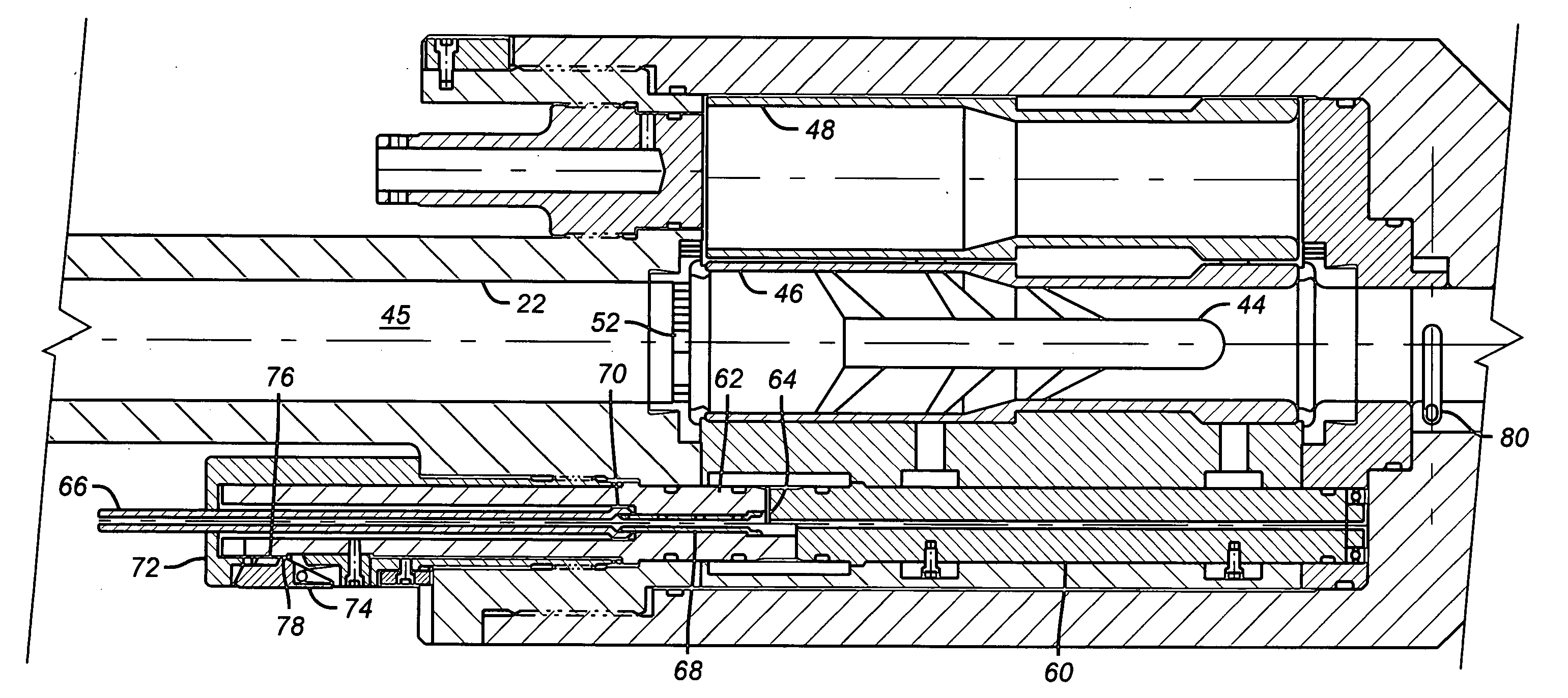
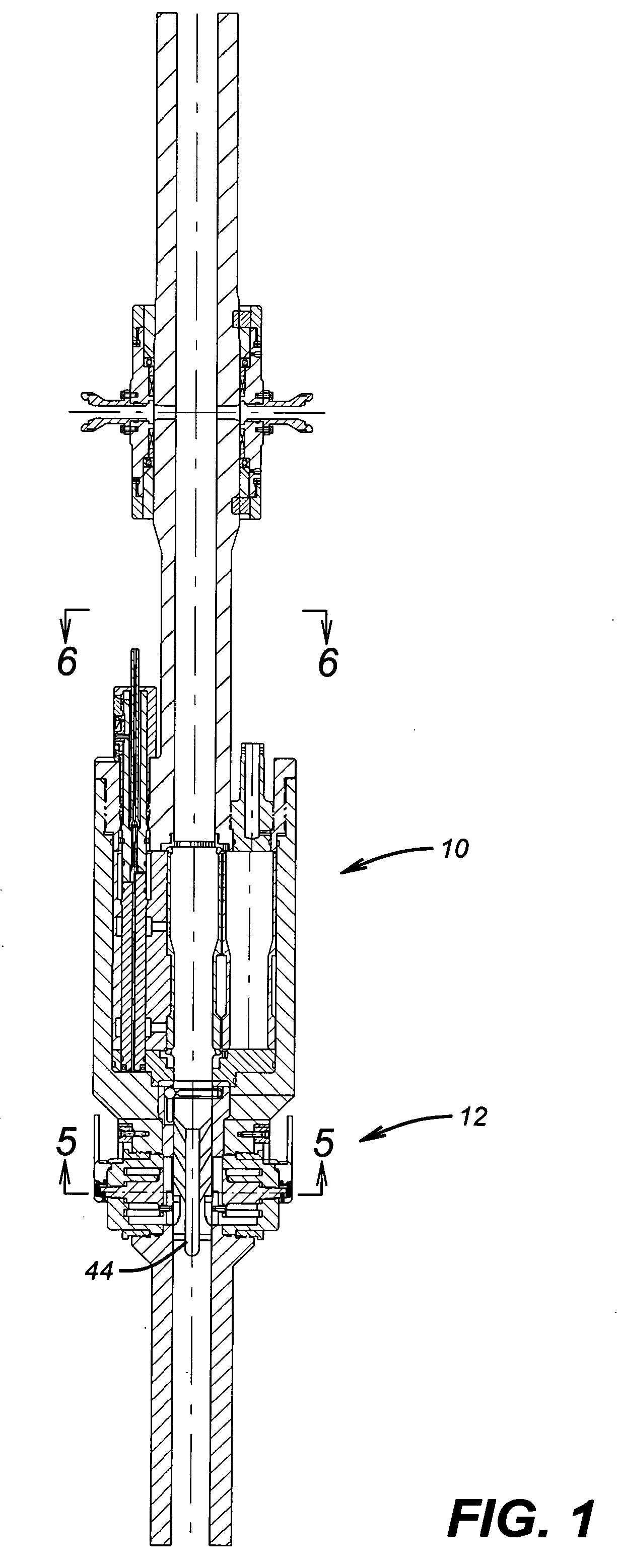
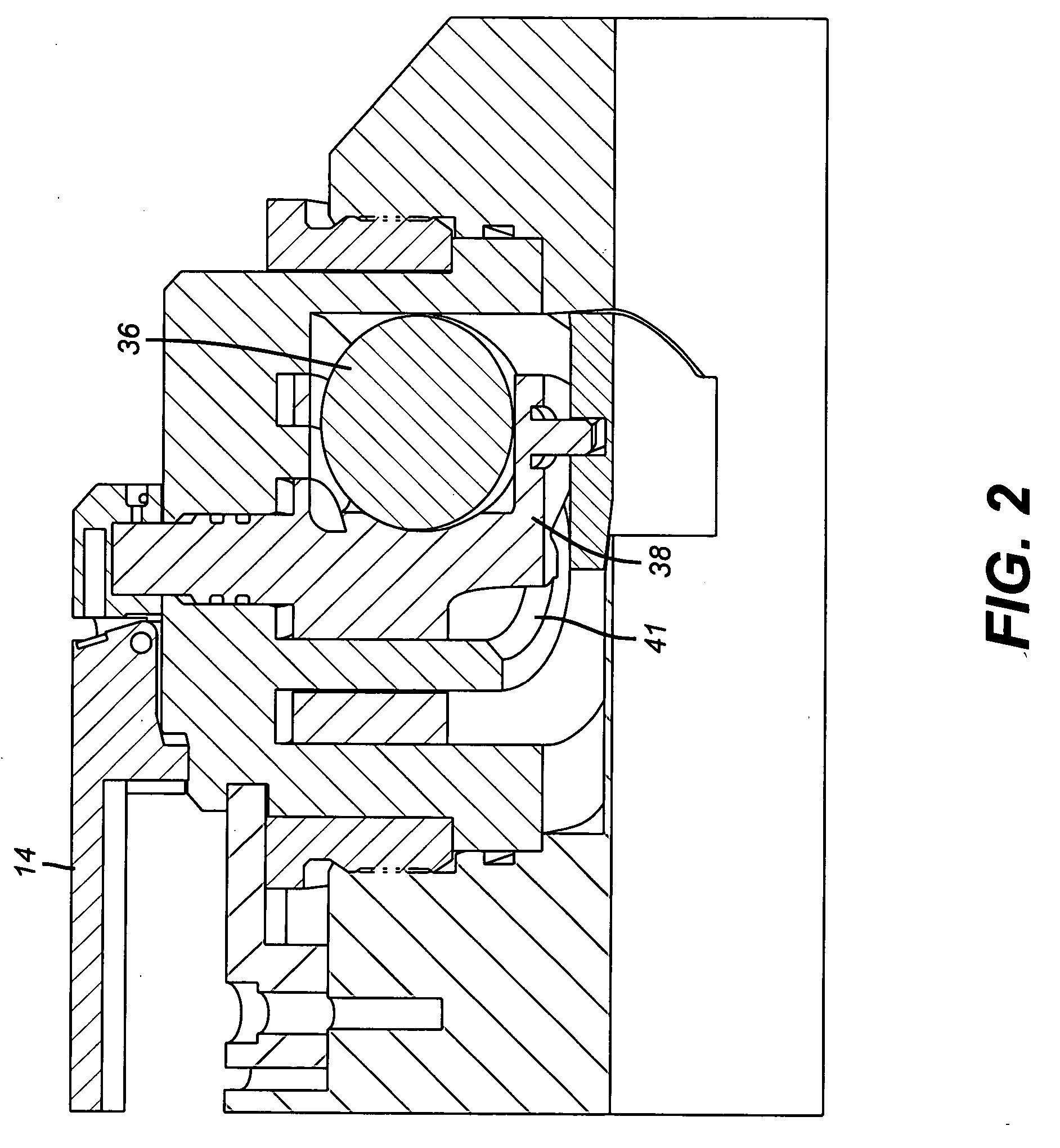
[0016] Referring to FIG. 1, the plug or dart dropping housing 10 is mounted above the ball dropping housing 12. While one of each is illustrated those skilled in the art will appreciate that more than one of each can be used. The housing 12 is shown in greater detail in FIGS. 2-4. FIG. 4 will be used to describe the components of the housing 12. A handle 14 is mounted for 360 degree rotation of a cam 16. The handle 14 is secured by a pin 18 to cam 16. The casing or tubular 20 has an interior wall 22. A door 24 has a curved surface 26 designed to approximate the curvature of the interior wall 22 of the casing 20 when in the position shown in FIG. 4. The cam 16 has a guide rod 28 that extends into the door 24. A spring 30 surrounds rod 28 to bias the door 24 into a position where curved surface 26 is positioned as close as possible to the interior wall 22. Door 24 has an upper tapered surface 32 to ease its travel path up the outside wall 34 of the casing 20 when the handle 14 is rota...


PUM


Abstract

A tool for dropping one or more balls and then one or more darts features a closable ball drop opening that works automatically after the ball release to minimize damage to the subsequently released dart. A retainer keeps the darts from coming back up above the dart launcher in the event of a pressure surge in the well. The dart launcher features a dedicated movable barrel for each dart that can be locked in a fully misaligned and fully aligned position with the casing or tubular. A handle is retained to the dart housing and can be manipulated to defeat the lock and rotate a given barrel. The darts may be inspected in their respective barrels before launch and the launch order is variable.

Description

PRIORITY INFORMATION [0001] This application claims the benefit of U.S. Provisional Application No. 60 / 591,058, filed on Jul. 26, 2004.FIELD OF THE INVENTION [0002] The field of this invention related to surface cementing heads for dropping balls and wiper plugs into a wellbore. BACKGROUND OF THE INVENTION [0003] In cementing casing or liners the procedure typically involves dropping one or more balls for engagement with a downhole seat sized for that ball to allow pressure buildup to set downhole devices such as external casing packers. After the ball is dropped and the downhole equipment is set, the delivery of the cement occurs in conjunction of delivery of one or more wiper plugs or darts down the casing. These plugs separate mud from cement or clean the inside of the casing. [0004] Typically the ball-dropping device is located below the dart-releasing device so that the darts must travel past the ball-releasing device after it has dropped the balls. One problem with this layout...

Claims


Application Information

Patent Timeline
Patent Type & Authority Applications(United States)
IPC IPC(8): F42D3/00
CPCE21B33/05E21B23/00E21B33/068E21B43/10
Inventor ARCE, DAVID A.BAUGH, JOHN L.SMITH, SIDNEY K.
Owner BAKER HUGHES INC
Why Eureka
Try Eureka