
Adhesive film sticking apparatus

a technology of adhesive film and stick, which is applied in the direction of packaging, labelling, labelling machines, etc., can solve the problems of difficulty in reliably detecting the presence of adhesive film by some optical sensors such as the photosensor, and the adhesive film cannot be stably set in place,

Inactive Publication Date: 2006-02-09
NITTO DENKO CORP
View PDF10 Cites 4 Cited by
  • Summary
  • Abstract
  • Description
  • Claims
  • Application Information

AI Technical Summary

Benefits of technology

[0015] The present invention has been made in view of the above circumstances and has an object to overcome the above problems and to provide an adhesive film sticking apparatus capable of setting adhesive films in a predetermined sticking position by reliably detecting the edge of each adhesive film adhered and spaced at predetermined intervals on a base tape even where the adhesive films are films having a light transparent property.
[0016] Another object of the present invention is providing an adhesive film sticking apparatus that can flexibly be operate for various types of adhesive films different in size to individually set the adhesive films of any size in a predetermined sticking position.
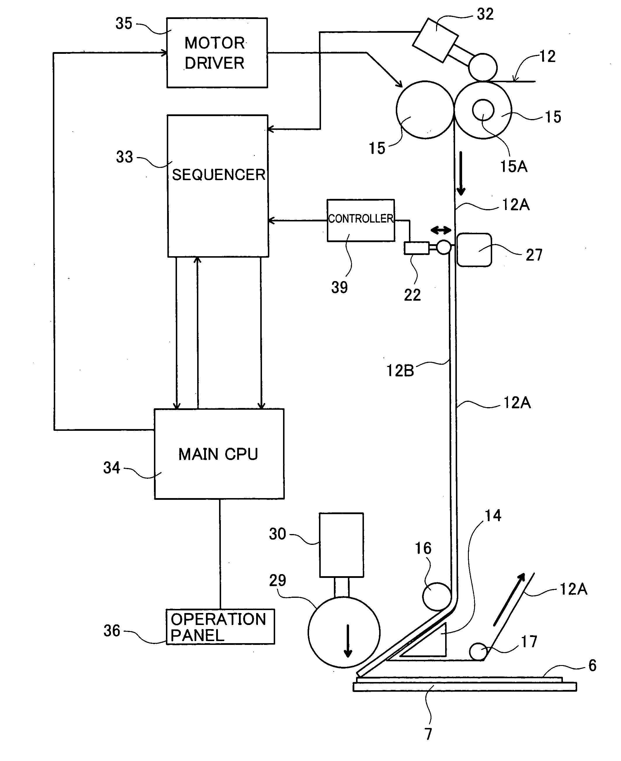
[0024] The above sticking apparatus is arranged such that, based on the detection signal output when the detection device detects the edge of each adhesive film, the tape feed device feeds the film supply tape by the predetermined amount, setting each adhesive film in the predetermined sticking position corresponding to the fold-back point of the film supply tape. The position of the detection device placed in the sticking apparatus can freely be set, which makes it possible to hold a high level of the design freedom of the sticking apparatus.
[0026] The adhesive film sticking apparatus (3) further comprises the guide bar having a flat support surface placed to face the roller contactor of the detection device having the rotatable roller, interposing the film supply tape between the guide bar and the roller contactor. For detection of each adhesive film on the film supply tape, the roller contactor is pressed against the support surface of the guide bar. Accordingly, the detection device can definitely detect the displacement of the roller contactor corresponding to the thickness of each adhesive film, thereby stably detect the end of each adhesive film.
[0027] The adhesive film sticking apparatus (4) is arranged such that the roller contactor of the detection device is separated from the support surface of the guide bar during non-operation in which the tape feed device does not feed the film supply tape. Accordingly, the work of placing the film supply tape along the predetermined path in the sticking apparatus is easily achieved. Further, it is possible to certainly prevent unnecessary stress on the roller contactor to stably keep the detection accuracy of the detection device for a long term.

Problems solved by technology

In the case where the adhesive film is made of a transparent or semitransparent film having a light transmittance property, however, it is very difficult for some optical sensors such as the photosensor to reliably detect the presence of such adhesive film.
In this case, the adhesive film could not be set stably in place.
This apparatus can be operated for adhesive tapes having a uniform size arranged on a release tape; however, it is unsuitable for various-sized adhesive tapes for various-sized substrates.
Although the tape detecting mechanism can be freely moved according to the size of each adhesive tape, a work of adjusting the position of the tape detecting mechanism would be extremely troublesome.

Method used


Image

  • Adhesive film sticking apparatus
  • Adhesive film sticking apparatus
  • Adhesive film sticking apparatus

Examples


Embodiment Construction

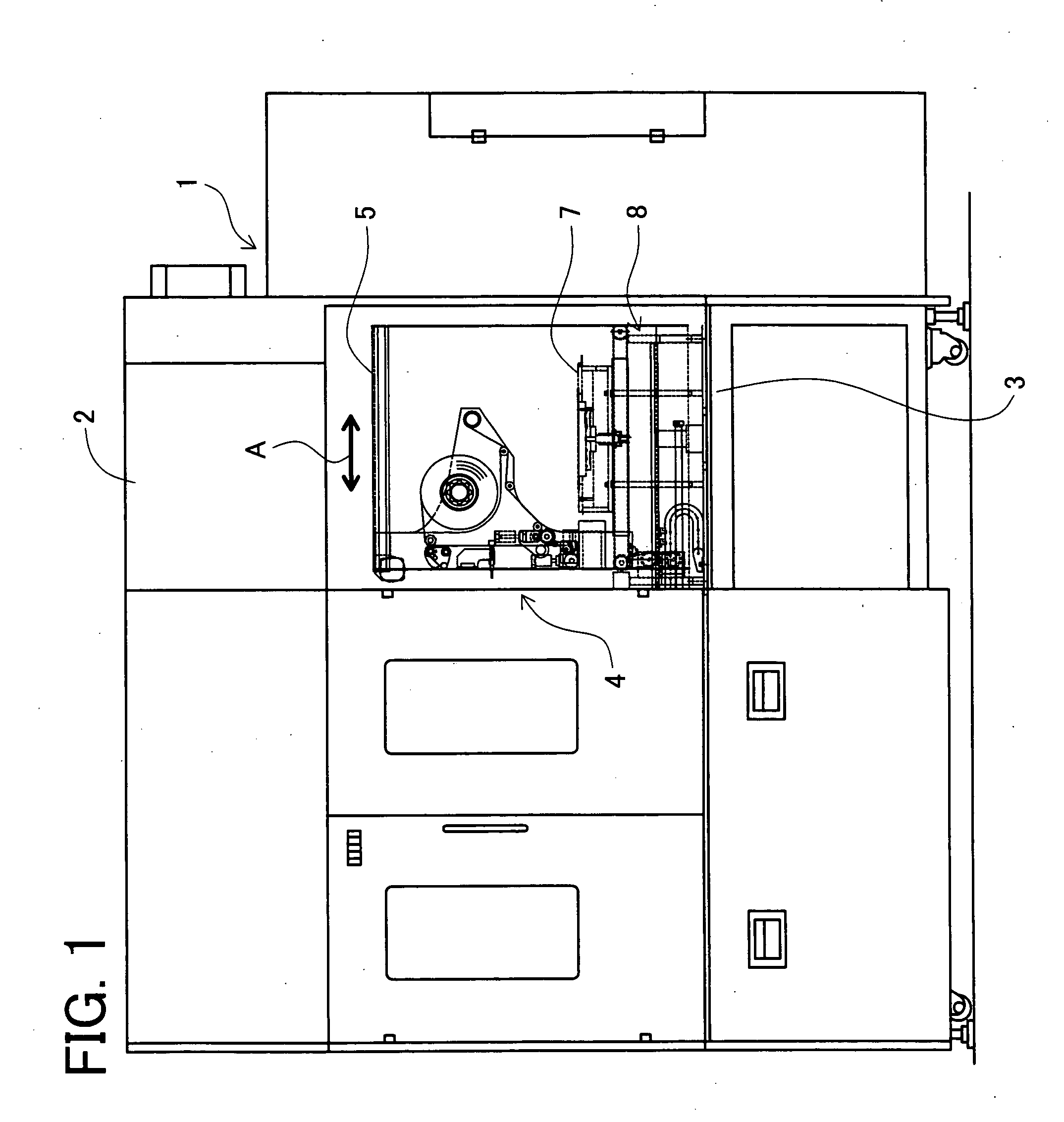
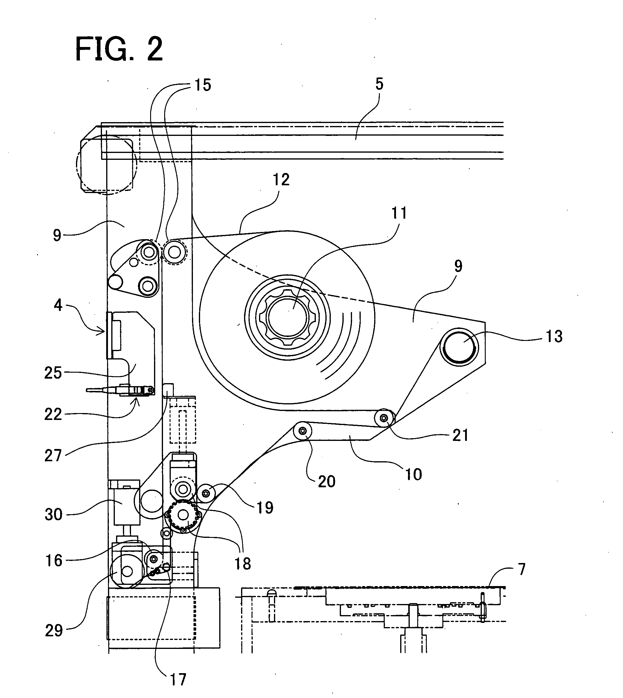
[0040] A detailed description of a preferred embodiment of an adhesive film sticking apparatus embodying the present invention will now be given referring to the accompanying drawings. At first, a schematic structure of the adhesive sticking apparatus in the present embodiment will be explained with reference to FIGS. 1 and 2. FIG. 1 is a side view of the adhesive film sticking apparatus. FIG. 2 is an enlarged view of a film sticking unit attached to the adhesive film sticking apparatus.

[0041] In FIGS. 1 and 2, the adhesive film sticking apparatus 1 includes an apparatus body 2 containing a work base 3 on which a sticking unit 4 is mounted. This sticking unit 4 is suspended from a rail 5 built in the apparatus body 2 and is arranged to reciprocate in a direction indicated by an arrow A in FIG. 1 by means of a driving device not shown. Placed below the sticking unit 4 is a driving mechanism 8 for moving up and down a table 7 on which a semiconductor substrate 6 (see FIG. 3) is place...


PUM

PropertyMeasurementUnit
Sizeaaaaaaaaaa

Abstract

For detection of an adhesive film adhesively provided on a base tape of a film supply tape, a front end of the adhesive film is detected based on the detection of a predetermined displacement amount of a roller contactor of a detection sensor, the roller contactor being displaceable in a direction of thickness of the adhesive film. Based on a detection signal from the detection sensor, feeding rollers and others are controlled to feed the film supply tape by a predetermined feeding amount until the front end of the adhesive film comes to near a fold-back point of the base tape by a guide member.

Description

BACKGROUND OF THE INVENTION [0001] 1. Field of the Invention [0002] The present invention relates to an adhesive film sticking apparatus for sticking an adhesive film, which has a shape corresponding to that of a substrate, on a surface of the substrate in a process of surface treatments for various types of substrates such as a semiconductor substrate and a glass substrate for a liquid crystal display. [0003] 2. Description of Related Art [0004] Heretofore, various types of film sticking apparatuses have been proposed to stick an adhesive film on a surface of each of various types of substrates, the adhesive film having a shape corresponding to the shape of each substrate. [0005] For example, Japanese unexamined patent publication No. H7(1995)-195527 discloses an adhesive film sticking apparatus having the following structure. A film detecting mechanism detects that a headmost one of adhesive films placed on a film supply tape being fed by a film feeding means has reached a fixed p...

Claims


Application Information

Patent Timeline
IPC IPC(8): B65C9/18
CPCY10T156/1707B29C63/02B29C65/48B29C65/52
Inventor HIRAI, SHUUJIIRIE, MASARUNAGATA, NORIYOSHIYAMAMOTO, MASAYUKI
Owner NITTO DENKO CORP
Learn More