
Chiral polarization ultrawideband slot antenna

a slot antenna and ultrawideband technology, applied in the direction of slot antennas, antennas, direction finders, etc., can solve the problems of affecting the performance of the uwb system,

Inactive Publication Date: 2006-02-09
NEXT RF
View PDF9 Cites 39 Cited by
  • Summary
  • Abstract
  • Description
  • Claims
  • Application Information

AI Technical Summary

Benefits of technology

The technical effect of this patent is to create a small wireless antenna that works well for high-speed data transmission without causing any problems during use.

Problems solved by technology

The technical problem addressed in this patent is how to create a spiral antenna that meets the requirements of commercial ultrwideband (UWB) systems without being too wide in its bandwidth, making it harder to achieve regulation compliance, while also minimizing dispersion caused by the natural properties of the material used to construct the antenna.

Method used


Image

  • Chiral polarization ultrawideband slot antenna
  • Chiral polarization ultrawideband slot antenna
  • Chiral polarization ultrawideband slot antenna

Examples


Embodiment Construction

[0033] The principle of reciprocity requires that reception and transmission properties of an antenna be reciprocal so that properties of an antenna are the same whether the antenna is employed for receiving signals or is employed for transmitting signals. Throughout this description, it should be kept in mind that discussions relating to transmitting or transmissions apply with equal veracity to reception of electromagnetic energy or signals, and vice versa. In order to avoid prolixity, the present description will focus primarily on reception characteristics of antennas, with the proviso that it is understood that transmission of energy or signals is also inherently described.

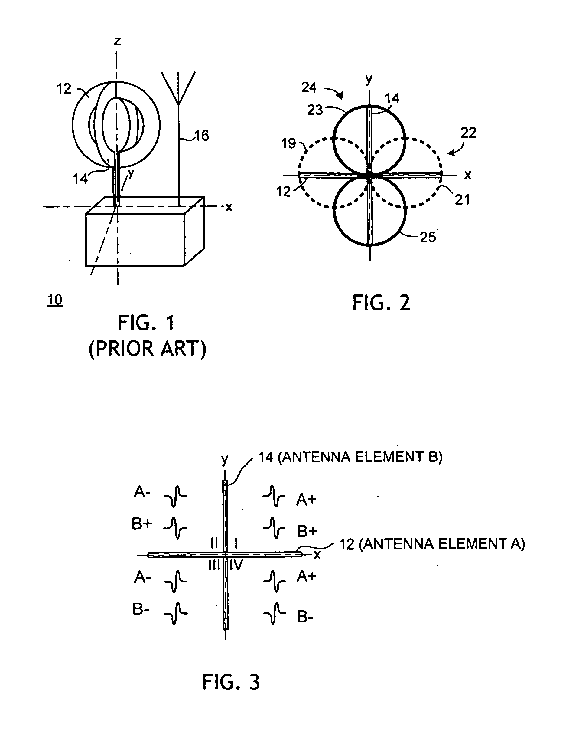
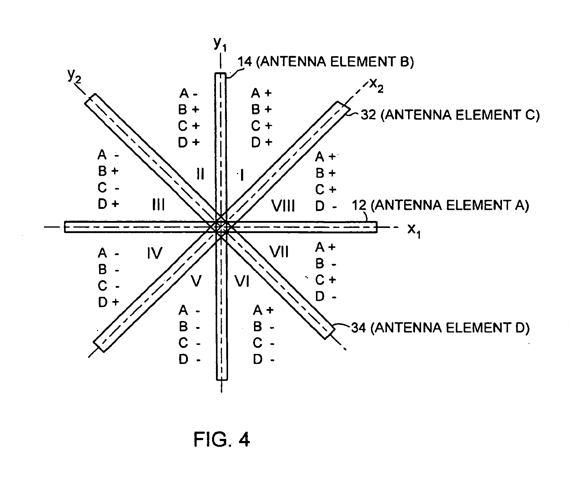
[0034]FIG. 1 is a schematic diagram of a representative prior art antenna array useful for radio direction finding operations. In FIG. 1, a radio direction finding antenna array 10 includes a first vertically oriented loop antenna element 12 arranged substantially perpendicular with a first axis “y” and a se...


PUM


Abstract

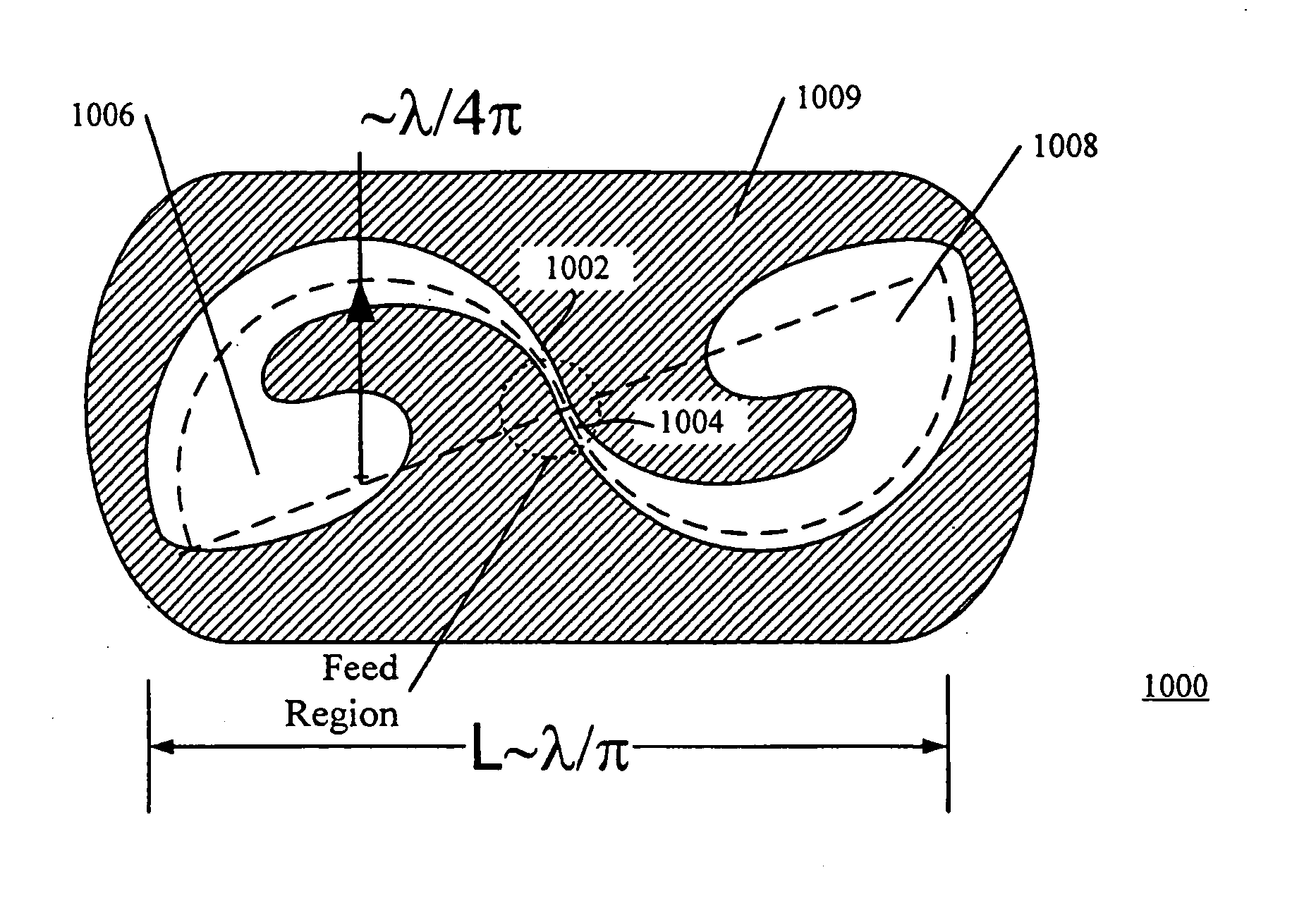
A chiral polarization UWB slot antenna comprises a feed region and opposing tapered slot lines along an arcuate path of angle measure 360° or less. Opposing tapered slot lines may terminate in bulbous ends and may be characterized by an impedance profile such as an exponential or a Klopfenstein impedance profile. In alternate embodiments, an arcuate path has an arc length substantially equal to a half wavelength at a frequency of interest and an angle measure substantially equal to 180°. In still further alternate embodiments an arcuate path is substantially described by a radial variation with respect to angle of r(φ)=R sin φ where R is a constant that in some embodiments is substantially equal to ½π times wavelength (R=λ/(2π)) at a particular frequency of interest. In some embodiments, a frequency of interest lies substantially within the range defined by 3.1 GHz to 10.6 GHz.

Description


Claims


Application Information

Patent Timeline
Owner NEXT RF
Learn More