

Network communication apparatus
- Summary
- Abstract
- Description
- Claims
- Application Information
AI Technical Summary
Benefits of technology
Problems solved by technology
Method used
Image

Examples
first embodiment
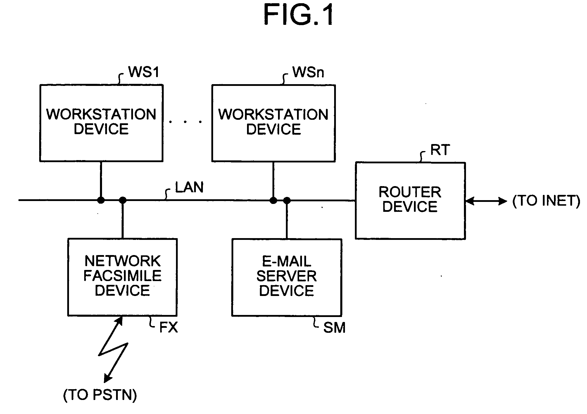
[0050]FIG. 1 is a block diagram of a network system according to the present invention. A plurality of workstation devices WS1 to WSn, an e-mail server device SM, a network facsimile apparatus FX, and a router device RT are connected to each other through a local area network LAN. Moreover, these devices are connected to the Internet through the router device RT. Accordingly, the workstation devices WS1 to WSn, the e-mail server device SM, and the network facsimile apparatus FX can exchange data with other terminal devices through the Internet.
[0051] The e-mail server device SM distributes and collects e-mails to and from a user using the workstation devices WS1 to WSn and the network facsimile apparatus FX.
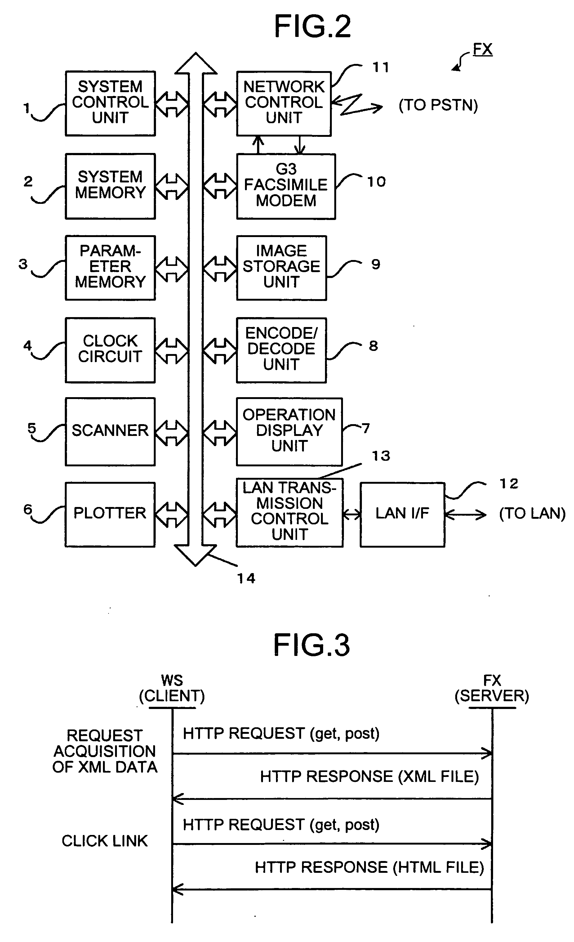
[0052] The workstation devices WS1 to WSn each include facsimile application software for creating, displaying, and outputting facsimile image data, and various programs such as software for exchanging data through the LAN. Each of the workstation devices WS1 to WSn is used by a...
second embodiment
[0133]FIG. 14 is a block diagram of a network system according to the present invention. FIG. 15 is a block diagram of a network facsimile apparatus FX2 shown in FIG. 14.
[0134] The network system shown in FIG. 14 and the configuration of the network facsimile apparatus FX2 shown in FIG. 15 are the same as those according to the first embodiment shown in FIG. 1 and FIG. 2; thus, overlapping descriptions are omitted. However, the components are denoted by different reference numerals.
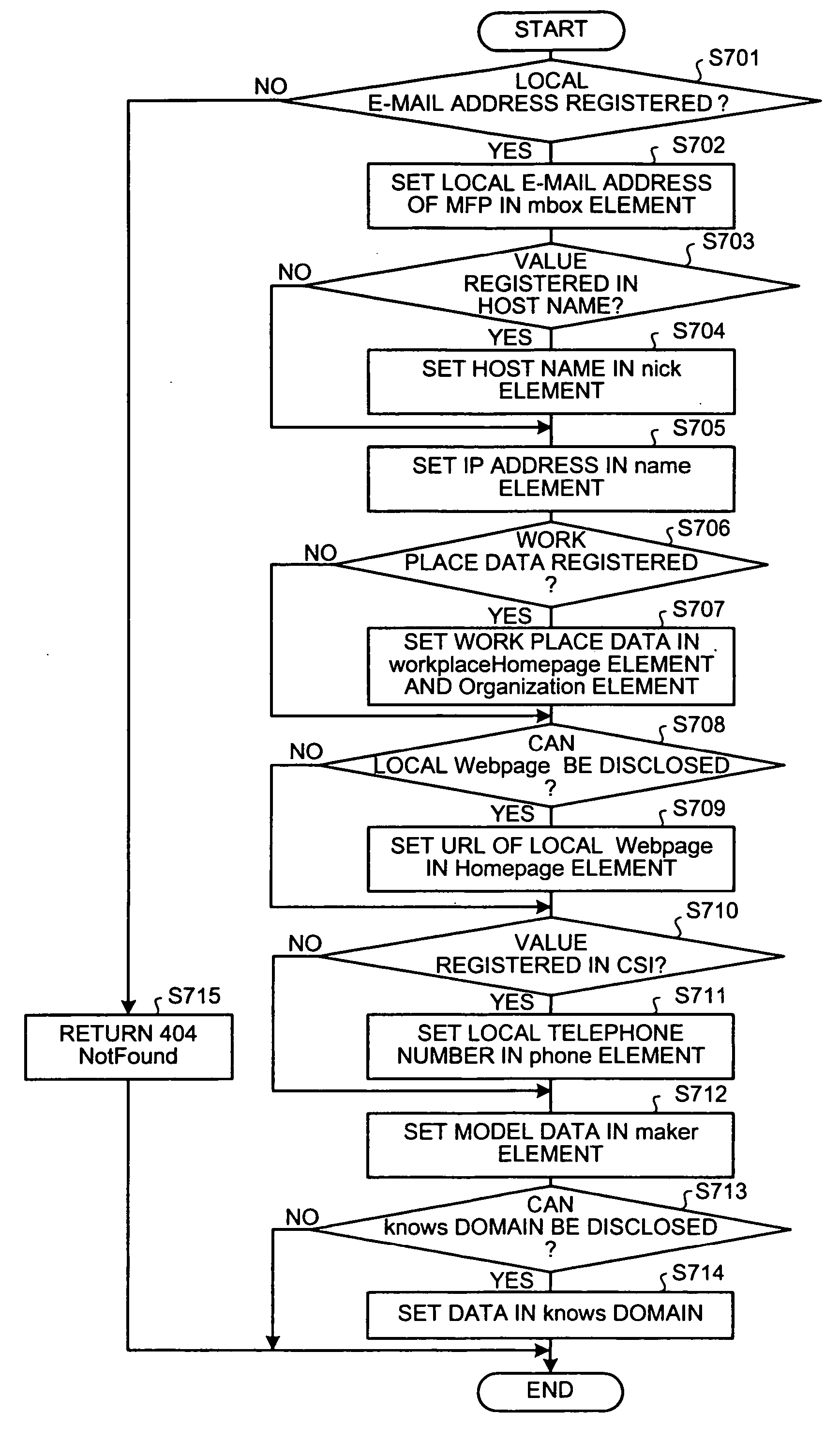
[0135]FIG. 16 is a time chart showing communication by the HTTP, according to the second embodiment. The difference from the first embodiment shown in FIG. 3 is that the network facsimile apparatus FX2 provides Friend-of-A-Friend (FOAF) data as a semantic XML document to the client device.
[0136] The present embodiment uses the FOAF to provide data of a terminal or a related terminal to another terminal. The FOAF vocabulary has been established for disclosing / sharing data of a person (oneself or a friend...
third embodiment
[0173]FIG. 23 is a diagram of a system configuration including a network communication apparatus 1c according to the present invention. The network communication apparatus 1c exchanges image data with a facsimile device 201 through a PSTN 200. If the network communication apparatus 1c has an interface for an integrated services digital network (ISDN) 300, the network communication apparatus 1c can exchange image data with a facsimile device 301 through the ISDN 300 (however, this is not included according to the present embodiment). The network communication apparatus 1c is connected to a LAN 100, and can exchange image with personal computers (PC) 101a, 101b, 101c, and a router device 102. The network communication apparatus 1c is connected to the Internet 400 through the router device 102 that converts packets. Through the Internet 400, the network communication apparatus 1c can exchange image data with a PC 402 by an e-mail, and exchange image data with a network facsimile appara...
PUM
 Abstract
Description
Claims
Application Information